I installed Home Assistant with Dokku. It was very easy, but there were a couple of gotchas that slowed it down a bit.

Setup

Create a new homeassistant app in Dokku

dokku apps:create homeassistant

Set the timezone

dokku config:set homeassistant TZ=America/Chicago

Create a folder that will be used for Home Assistant configuration

mkdir /path/to/my-config
dokku storage:mount homeassistant /path/to/my-config:/config

Home Assistant uses its own init procedure, and we need to disable automatic init

dokku scheduler-docker-local:set homeassistant init-process false

Initialize Home Assistant app from its docker image

dokku git:from-image homeassistant ghcr.io/home-assistant/home-assistant:stable

Dokku didn’t correctly configure the correct port for the container, so:

Remove the default proxy port if needed:

dokku proxy:ports-remove homeassistant http:80:5000

Add the correct proxy port:

dokku proxy:ports-add homeassistant http:80:8123

To enable autodiscovery, Home Assistant needs to be connected to the host network. Other than autodiscovery, I had no issues using the default network and normal port mapping.

You can enable this option in dokku with

dokku docker-options:add homeassistant deploy,run "--network=host"

Once Home Assistant is on the host network, dokku’s zero-downtime restarts will fail when updating or restarting the service, because the bound port will already be in use.

Zero downtime restarting can be disabled with

dokku checks:disable homeassistant

Updating Home Assistant

To update Home Assistant, use git:from-image again, pointing to the newest SHA digest for your architecture (instead of using the :stable tag)

dokku git:from-image homeassistant ghcr.io/home-assistant/home-assistant@sha256:<shadigest>

You can get this digest from docker hub for your architecture: docker hub, or you can pull the image locally and use:

docker inspect --format='{{index .RepoDigests 0}}' ghcr.io/home-assistant/home-assistant:stable

My favorite automations (so far) turn my printer’s light off automatically after a print completes, and lets me know to open windows when the weather is cooler and less humid outside, and air quality is ok.


I do a lot of multicolor 3d printing, where more than one color is printed on the same layer using manual filament swapping, and I wanted to share some tips that I haven’t seen collected everywhere.

3d printed game counter with multiple rings with inlayed numbers, with different colors for each ring.
Several multicolor prints for a TTRPG tracker

Some of this applies to layer/height-based color swapping, but this is directed specifically at the above, AKA the poor-man’s MMU.

This is pretty easy to set up in PrusaSlicer, and probably other slicers as well, but I don’t have as much experience with them.

Setup

First, create a new printer with two (or more) configured extruders, one extruder for each color you’d like to use in your print.

In the Custom G-code tab, set the Tool change G-code value to m600.

Tool change G-code field with the value 'M600`

This triggers a manual filament change when changing extruders.

Lastly, import your multipart object, select it and press the “Split To Parts” button in the toolbar.

Next, assign the appropriate extruder to each part in the part list.

PrusaSlicer parts list with multiple items selected. Context menu is open to the Change Extruder option with Extruder 2 highlighted

Extruder 1 will be used first, so use that one for the background color, and use extruder 2 for your inlay. Otherwise you’ll end up doing an extra color swap.

Rendered gcode preview showing the underside of a part with inlayed numbers in a different filament color
Ready to go

Tip 1: Minimizing filament swaps

Without an automatic filament changer, you’ll may want to minimize the number of manual filament swaps.

For top or bottom-layer inlays, I usually stick to a total of two colors, two layers thick. This allows two-color prints with a total of two filament changes.

Additional colors add one more swap per color per layer.

number_of_swaps = layer_count * (colors - 1)

Tip 2: Filament opacity

For text inlays and similar small details, you’ll want to use a filament that is as opaque as possible. Transparent colors, especially over dark “background” colors, will appear dim and muddy.

Black box with a small yellow inlayed border, compared to another part printed entirely with the same filament. The border's color is less intense, and darker
Two 0.3mm layers of yellow-orange over black, compared to a single colored part

When using a less opaque filament, a white or light colored filament for the background will be more forgiving.

A small test print is recommended to make sure your colors will look OK at the layer thicknesses you’re using, especially if your prints are large or complex.

Tip 3: Use a wipe tower

This actually serves two purposes. Obviously, it allows a reliable color change with configurable purge volumes without as much baby sitting while changing filament, but it also has another side effect.

Without a wipe tower, the m600 filament change event will take place when the extruder has completed the last object of that color for a layer, and when that’s complete, the extruder will return to the last location, before moving on to the next object location.

This can cause a small, circular dot of the new filament color in the last object location, which can be pretty noticeable with certain colors, or when printing on the top layer.

With a wipe tower, the extruder will first be moved to the wipe tower area, then initiate swap filament, and then will return to the wipe tower for purging, which prevents the wrong-color-spot.

The tower is still very efficient for prints where the bottom layer(s) have a color change, since the wipe “tower” will only be two layers thick.

Gcode preview with short, rectangular wipe tower alongside part to be printed
Small wipe tower

Tip 4: Z-hop

On layers where there will be filament swapping, add a small Z-hop. This prevents any small blobs from getting dragged across the printed surface. This is not usually noticeable with single color prints, but can stand out more with contrasting colors. The z-hop setting prevents this by raising the extruder up a little bit for travel moves.

In PrusaSlicer, this is configured per extruder (so you’ll need to set it more than once) under Printer Settings -> Extruder x, under “Lift Z”. You’ll need to enable retraction if you don’t already, or the setting will be disabled. You can limit the range where Lift Z is enabled in the setting below it.

PrusaSlicer retraction printer settings. Lift Z is set to 0.2mm, between the range of 0 and 0.6mm Z heights
Lift Z Settings
Gcode preview with travel moves displayed, with visible vertical moves when traveling to and from colored sections
Lift travel moves

The word hello centered inside a circle in CascadeStudio

I’ve been using CascadeStudio recently for parametric modeling (like this) and needed a way to center some dynamic text, which isn’t implemented currently.

Fortunately, a user on github documented a way to get the boundary box of a solid shape here: this discussion post, which makes centered (or right-aligned) text easy.

// https://github.com/zalo/CascadeStudio/discussions/86#discussioncomment-506883
const getBounds = shape => {
    const bmin = { x: Infinity, y: Infinity, z: Infinity },
        bmax = { x: -Infinity, y: -Infinity, z: -Infinity };

    ForEachFace(shape, (index, face) => {
        ForEachVertex(face, (vertex) => {
            const pnt = oc.BRep_Tool.prototype.Pnt(vertex);
            const x = pnt.X(), y = pnt.Y(), z = pnt.Z();

            if (x < bmin.x) bmin.x = x;
            if (y < bmin.y) bmin.y = y;
            if (z < bmin.z) bmin.z = z;

            if (x > bmax.x) bmax.x = x;
            if (y > bmax.y) bmax.y = y;
            if (z > bmax.z) bmax.z = z;
        });
    });
    return [bmin, bmax];
}

// create the text shape
const textShape = Text3D("hello!", 10, 0.1);

// get the minimum and maximum bounds for the text
const [min, max] = getBounds(textShape);
const width = max.x - min.x;
const height = max.z - min.z;

// translate the text by half the width and height
Translate(
    [-width / 2, 0, -height / 2],
    textShape,
    false);

Demo link


I built this last year, but completely forgot to post about it. As such, it’s a bit detail-light.

Okay2 synth with closed case

Reasoning

I was looking for a small keyboard that I could use to sound out musical phrases or chords, while learning other instruments.

Notably, I wanted:

  • 1.5 to 2 octaves of notes
  • Standard piano layout
  • Small enough to fit in my desk drawer, around 10.5” wide by 9” deep
  • Two or more note polyphony
  • Buttons for keys (rather than a stylophone)
  • Close enough to accurate tuning

There are some midi controllers that meet these requirements, but I was looking for something standalone, with it’s own speaker.

I couldn’t find any commercial keyboards that did those things, but I did eventually stumble on the (delightful) Oskitone site.

They have a number of fun noise makers, including the poly555, an analog keyboard based on twenty 555 timers, and the scout, a hackable microcontroller-based synth.

A number of these also have 3d models available for 3d printing:

https://www.thingiverse.com/oskitone/designs

I settled on the Okay2 synth, as it had the dimensions I was looking for (around 9.25” wide by 4.25” deep), two octaves of keys, and it looks cute.

Build

Internal wiring
Internal wiring

Instead of using Oskitone’s components, I chose to build out the internals myself. Initially, my goal for this was just to allow more notes to be played simultaneously, but the features got away from me a little as the project went on.

It currently supports the following:

  • full polyphony
  • eight sampled instruments, pulled from Microsoft’s sound fonts
  • selectable octave
  • volume control
  • headphone jack (as soon as I hook it up. I may never)

Components

For the controller, I settled on the Teensy 4.1, a high powered ARM development board, and their audio adapter board.

I chose a 2.5w class D amplifier and a 4ohm 3w speaker from Adafruit, as well as some 8 way rotary selector switches, and a potentiometer.

I purchased the PCBs for the keyboard itself from the designer. While it acts as a resistor ladder by default, I had enough open pins on the Teensy to allow one input per key, so I didn’t bother to wire up a matrix.

Keyboard PCB from Oskitone

Ideally, I’d have had a couple of custom PCBs made that would have simplified the wiring and build a lot, but at the time I had not done so before.

I made a handful of tiny changes to the case to accommodate my parts, mostly adding board standoffs in the right location, moving and adding potentiometer/switch holes in the lid, and resizing the hole for the speaker to match the one I used.

Testing speaker grills

I soldered everything together on a protoboard.

For power, I’m using 4 rechargeable AAA batteries.

Software

The project code is available here: https://github.com/Billiam/okay-teensy

All together now

Initial breadboard testing

Breadboard, now with volume and selector switches
Breadboard diagram
Breadboard diagram

Done!


Grbl smooth jogging

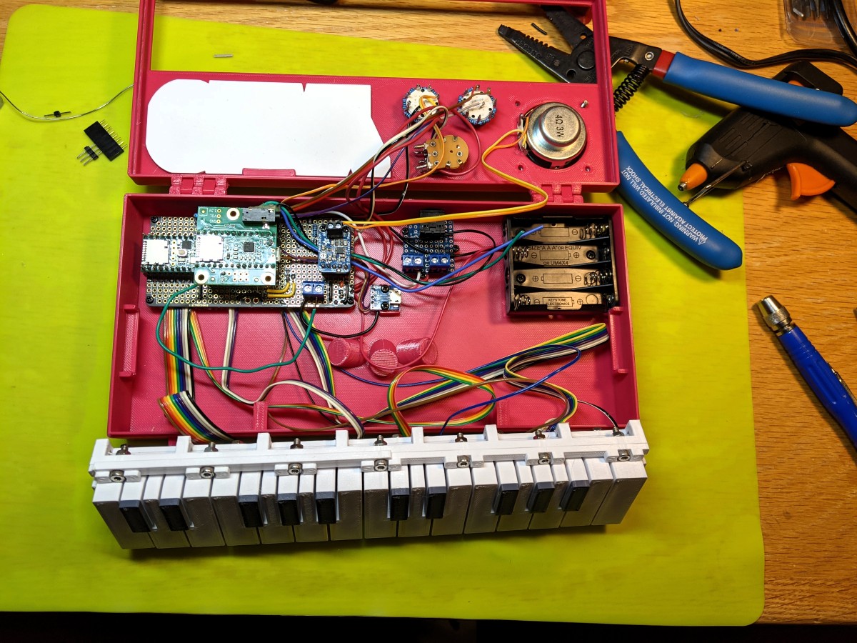
I’m working on a pendant for my CNC, running Grbl 1.1f, and wanted to add smooth multiaxis jogging. I’ve already done a single axis implementation for this project: https://github.com/Billiam/cncjs-pendant-keyboardreader

This took me a little bit to find my way through, so I’m documenting it here.

Here’s a good introduction to the feature: https://github.com/gnea/grbl/wiki/Grbl-v1.1-Jogging

Smooth jogging implementation

This implementation uses the GRBL 1.1 modal jogging functionality, but not the \x85 jog cancel feature, which has not yet been added in CNCjs at the time of this writing. cncjs#512

note: Decimal places below are rounded for simplicity

For a single axis

The goal here is to send frequent, small jog commands at the frequency that we expect grbl to execute them. Without jog cancel, there will be some amount of overtravel equal to 0.5 - 1.5x the update frequency (not counting network latency).

My setup includes some wifi usage, so my update frequency is relatively high at 150ms. For direct-only connections (like a touchscreen connected directly to the cncjs server), this could and should be much lower and will feel more responsive to both starting and stopping.

To move one axis at 500 mm/min, divide the total distance to travel in a minute by the update interval to get the total distance to travel for the interval `(500_("mm")) * (150 // 60*1000) = 1.25_("mm")// 150_("ms")`

And then issue the jog command: $J=G91 X1.25 F500, and then continue issuing the same jog command every 150ms until you want motion to stop.

I issue the first delayed jog command with a reduced delay, about 100ms instead of 150ms. This helps to keep grbl’s buffer full, so that it doesn’t try to decelerate each jog step to a stop, which results in jerky movement. This reduced delay should ideally be based on axis acceleration settings and variation in latency.

When (and if) jog cancelling is added in cncjs, the cancel command could also be added at the end of movement. Ideally, this would also allow you to exceed the requested travel distance for smoother jogging, since a jog stop could be issued when needed.

I haven’t come up with a way to do this safely that wouldn’t result in dangerous overshooting if the jog cancel command failed, or when using multi-axis jogging (below) though.

For multiple axes

Multiple axis smooth jogging is a little more complicated. I also want the Z axis to move about 4 times slower than the much larger X and Y axes, meaning I’ll have a ratio of axis speeds like x:y:z -> 1 : 1 : 0.25.

This is also important if using a multi-axis analog controller like a joystick/gamepad, or some wild 3+axis one: Each direction component will have its own speed relative to the others.

When you give grbl a jog command: $J=G91 X5 Y5 Z5 F500, the total distance traveled will be `D^2=x^2+y^2+z^2`, or about 8.66mm, since it moves in a beeline from the starting position to this offset.

To get the desired jog distance for each axis (with different travel speeds), we have to do some math.

First, we can get the diagonal of a rectangular prism with side lengths of of x1, y1, and z1 from our speed ratios, `D = sqrt(x1^2 + y1^2 + z1^2 + "…")`. This represents the relationship of 1 unit of axis speed to the diagonal travel.

For my speeds, that’s `D = sqrt(1^2 + 1^2 + 0.25^2)`, about 1.436.

To get the actual X travel distance, it’s the X speed ratio (1), the X direction(-1 or 1), and the desired travel speed, and the diagonal component: `X_("axis travel") = (500 * -1 * 1)//D` for a total of ~348mm/min, or -0.87mm/150ms.

The slower Z axis can be calculated the same way: `(500 * 1_("direction") * 0.25_("speed"))//1.436`, or 87 mm/min, but we also know its speed is 0.25 × the X axis speed, so 0.25 × 348: 87 mm/min (0.2175/150ms).

This gives us the jog command: $J=G91 X-0.87 Y0.87 Z.218 F500.

Grbl will plan this move so that all axes arrive at the same time, and everything works great.

However, note that $J=G91 Z.218 F500 would not be correct for this feed rate, and will complete much more quickly than our 150ms interval, causing stuttering motion.

Instead, the feed rate needs to be reduced to the maximum speed of all the axes being moved (in this case, just 0.25 × 500): $J=G91 Z.218 F125.

This applies to multi-axis moves as well. If the speeds being used were y:0.6, z:0.25 (with no X component)

`D_("distance")^2 = 0.6^2 + 0.25^2 = 0.65`
`Y_("axis") = (500 * 1 * 0.6)//D = 461.55_("mm/min") (1.15//150_("ms"))`
`Z_("axis") = (500 * 1 * 0.25)//0.65 = 192_("mm/min") (0.48//150_("ms"))`
`F_("feedrate") = max(0.6, 0.25) * 500 = 300`

Result: $J=G91 Y1.15 Z0.48 F300