Billiam bio photo

Billiam

"Hey, sorry I haven't updated in a while. Life's been crazy, but I'll be back soon."

Etsy Github Itch.io Printables Mastodon Twitter
Feed

CNC Build

I’m trying to keep track of my CNC project all in one place. Here’s the whole thing in chronological order.

2020

CNC software, pen holder

After assembling the Mega V, I ordered some endmills and MDF for a supplemental wasteboard, and while waiting for those to arrive, I made a few pen holders t...

CNC spoilboard

The stock spoilerboard included with the MDF version of the Mega V uses t-nuts for workholding, but they’re pretty sparse to begin with (example here)

CNC workholding

After finishing the dovetail grooves, I started on workholding and clamps by designing and 3d printing some dovetail inserts and knobs.

CNC tool setter

I had some keyboard switches left over from a previous project, and wanted a more convenient process for changing bits during a job.

CNC toolholders

While working on some other projects, I mocked these guys up real quick to help organize some of the tools and accessories I’m using with my CNC right now.

2022

CNC tramming plate

Note: This is an older (2+ years old) project, and there are now better third party options available (check Millright groups on facebook), even completely r...

Grbl smooth jogging

I’m working on a pendant for my CNC, running Grbl 1.1f, and wanted to add smooth multiaxis jogging. I’ve already done a single axis implementation for this p...

I preordered the Millright Mega V CNC router in October, and it feels like I should write something about it.

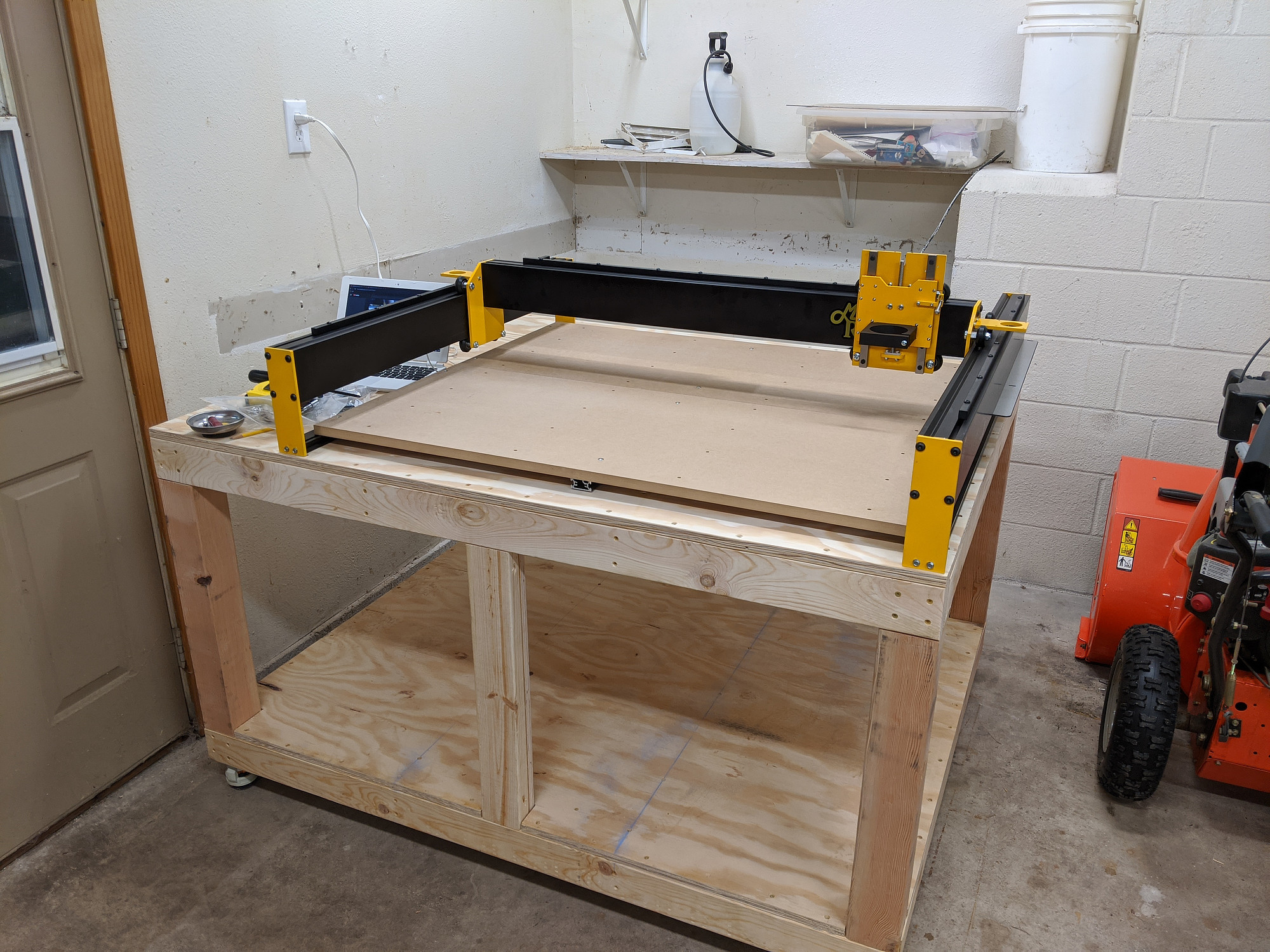
I have a small workspace in the corner of my garage, so naturally I ripped out most of it to make room for the 35” machine instead of something smaller and more practical for my space.

When I bought it, it wasn’t scheduled to ship for a few months While waiting, I took a stab at a basic table design to keep the machine at a comfortable working height, and to allow some storage for tools and dust collection.

CNC table
CNC table
Underside view
Underside view

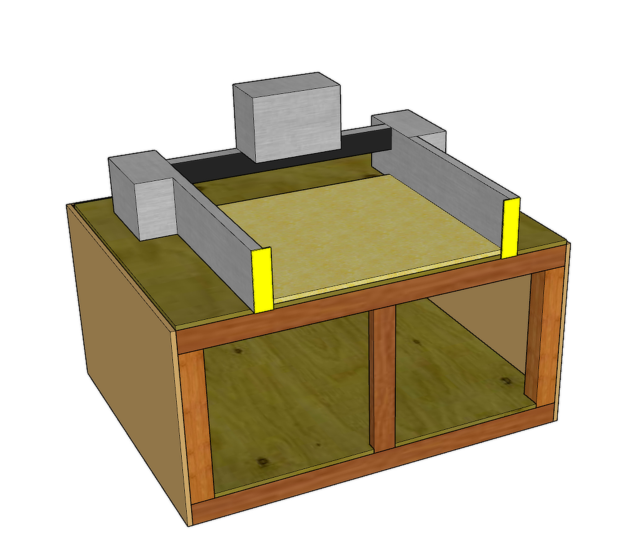
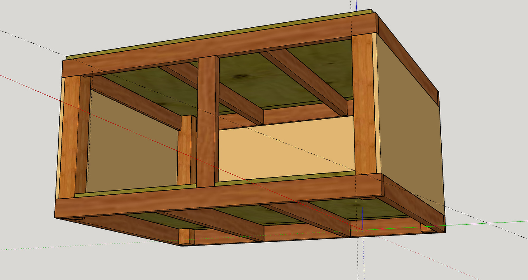
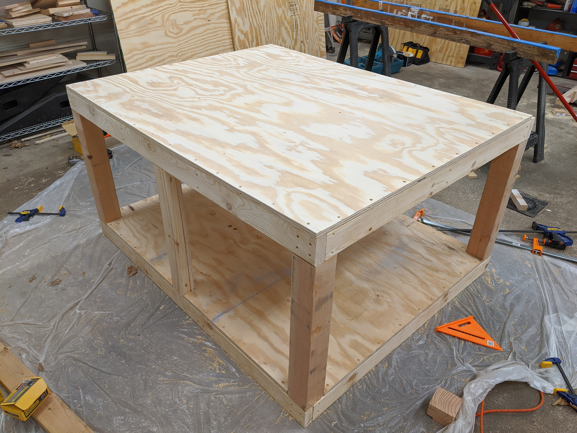
This is a very simple 2x4 and 4x4 box (in line with my woodworking ability), with a plywood top and MDF sides. Eventually, the front will have cabinet doors, and the top will be enclosed with a hinged lid to keep the sound level down.

I went back and forth about putting the whole thing on casters, whether they should be raisable so that the box is sitting on solid wood when stationary, how much the box and table would weigh, and most importantly how well they could be used with the table tucked into a corner when only of the feet/casters might be accessible.

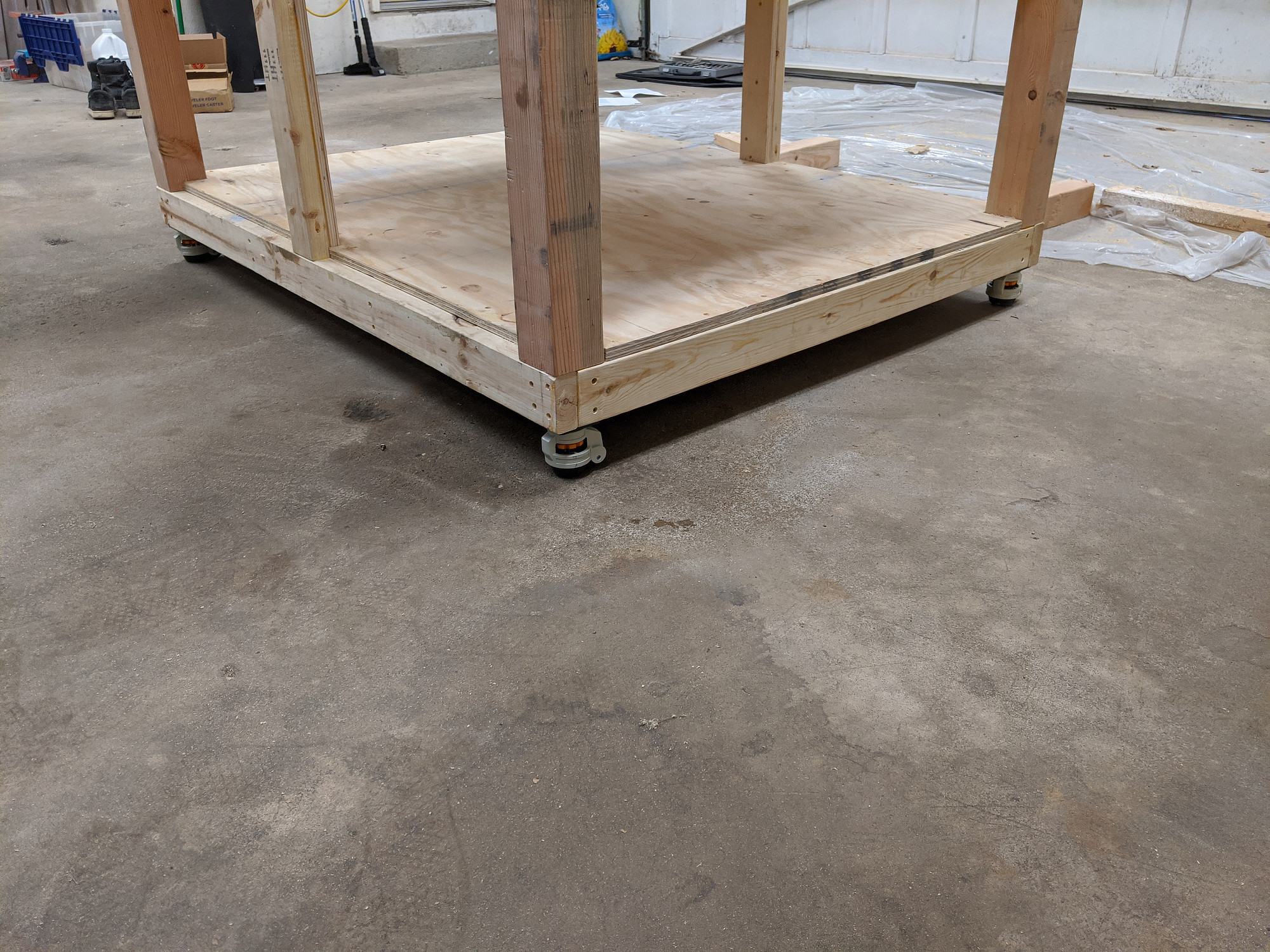
Eventually, I settled on these: https://smile.amazon.com/gp/product/B07V1NTLDP

They work well, but are difficult raise and lower once weighed down. I’d like to replace them but haven’t yet found an alternative.

Parts arrive

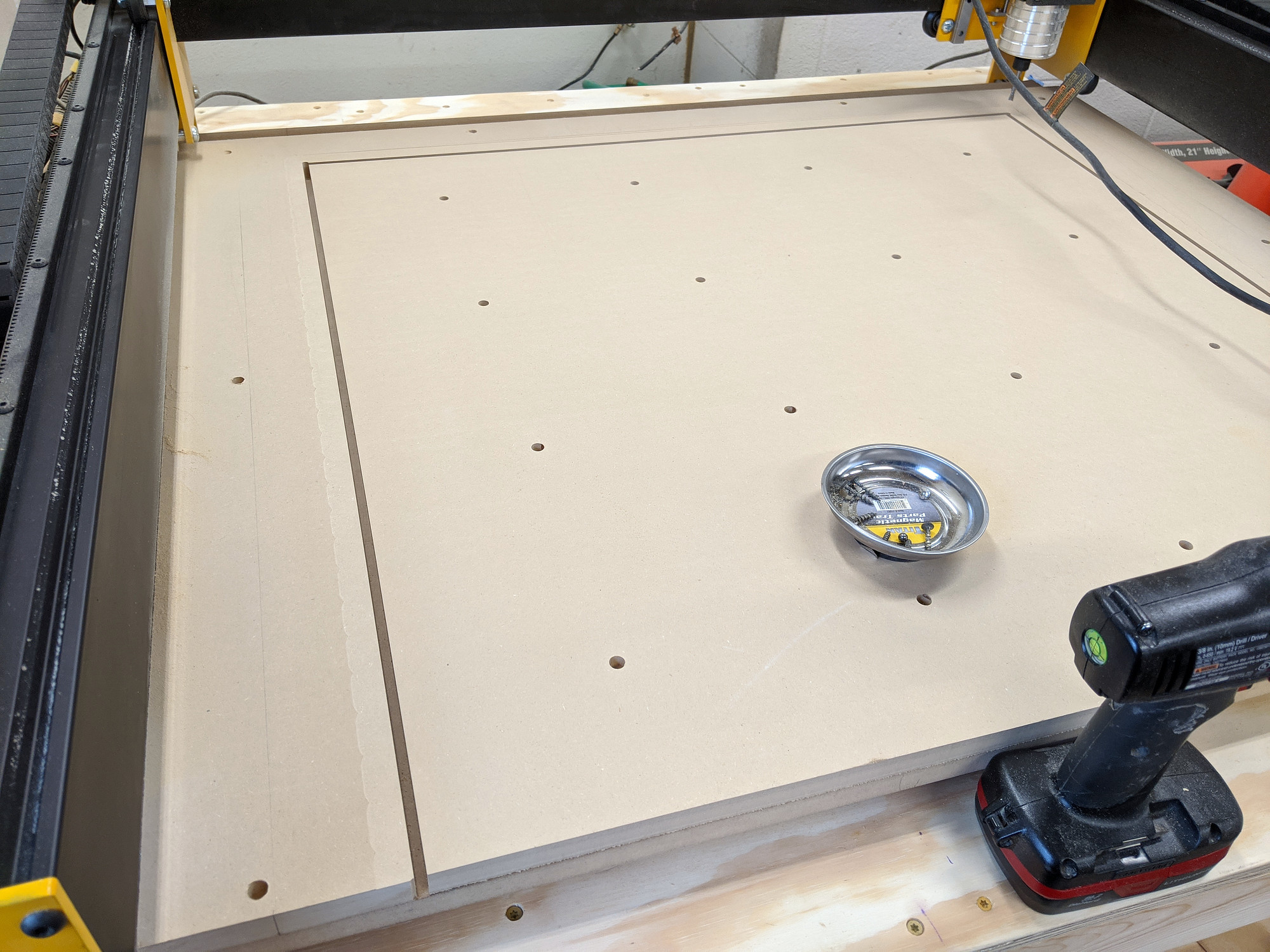
Got all my parts. I think I was missing a couple of screws, and there was a little shipping damage to the MDF spoilboard

Parts unpacked
Parts unpacked

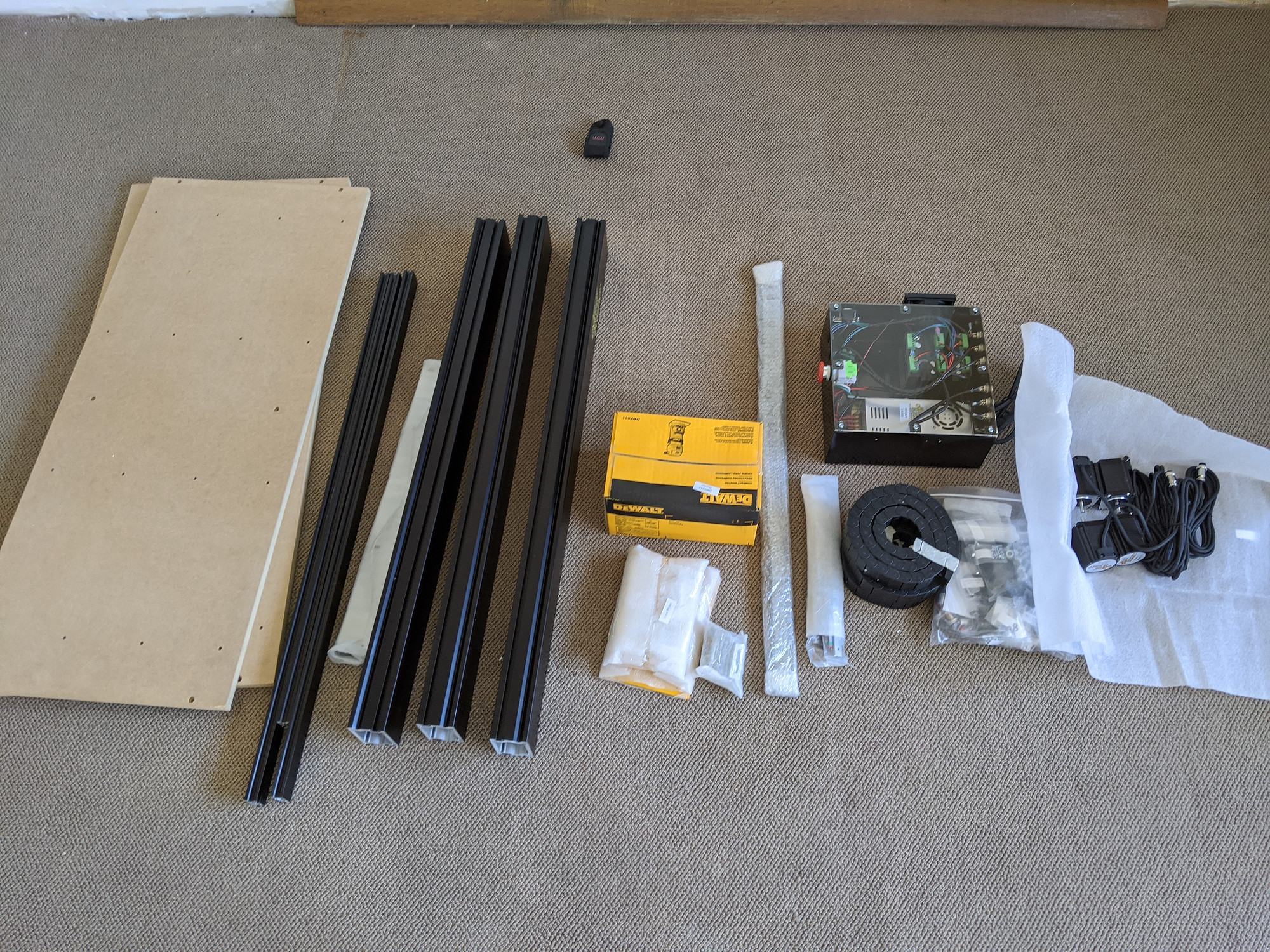
I put together what I could before building a cabinet for the CNC but it didn’t take long.
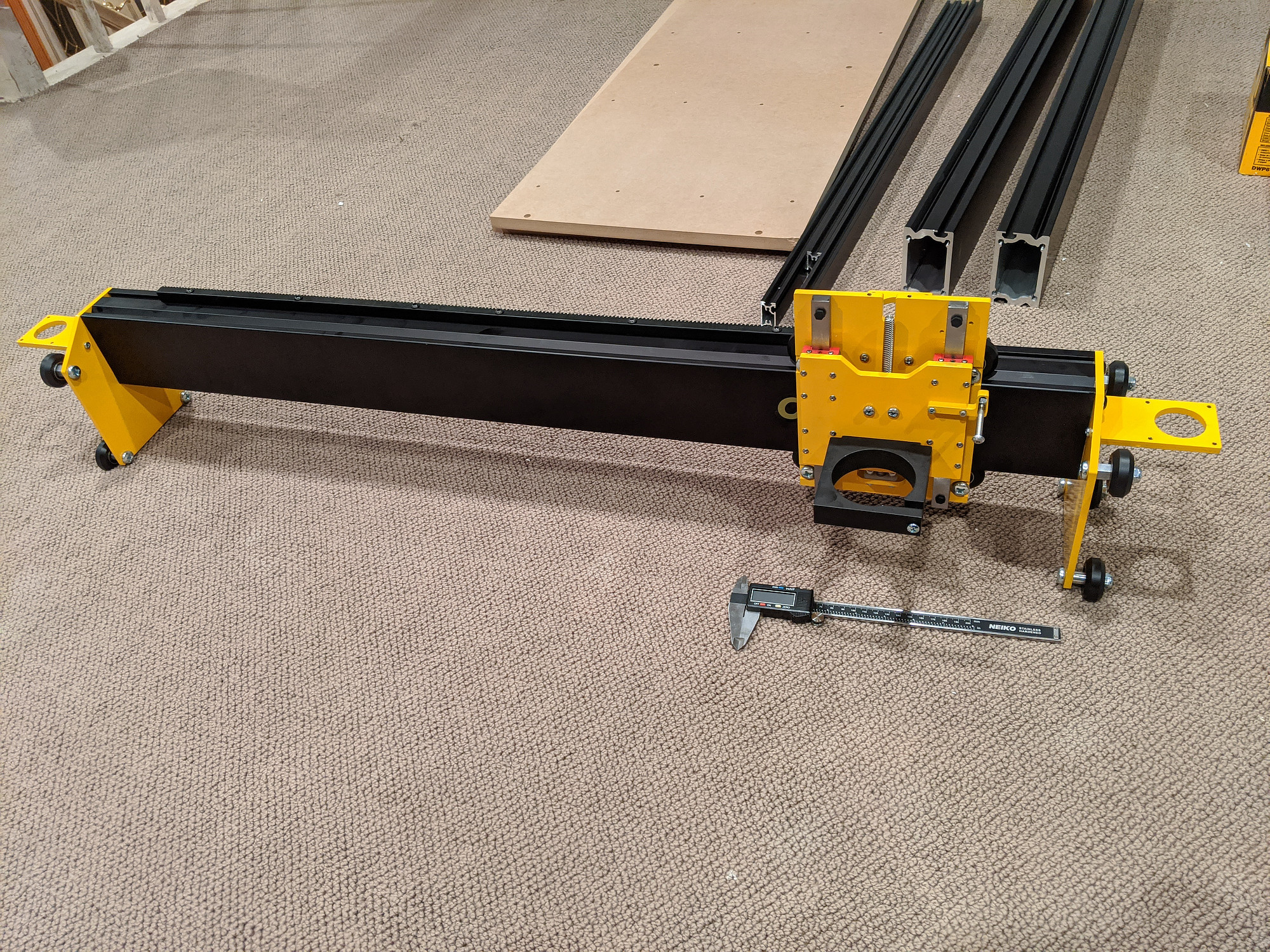
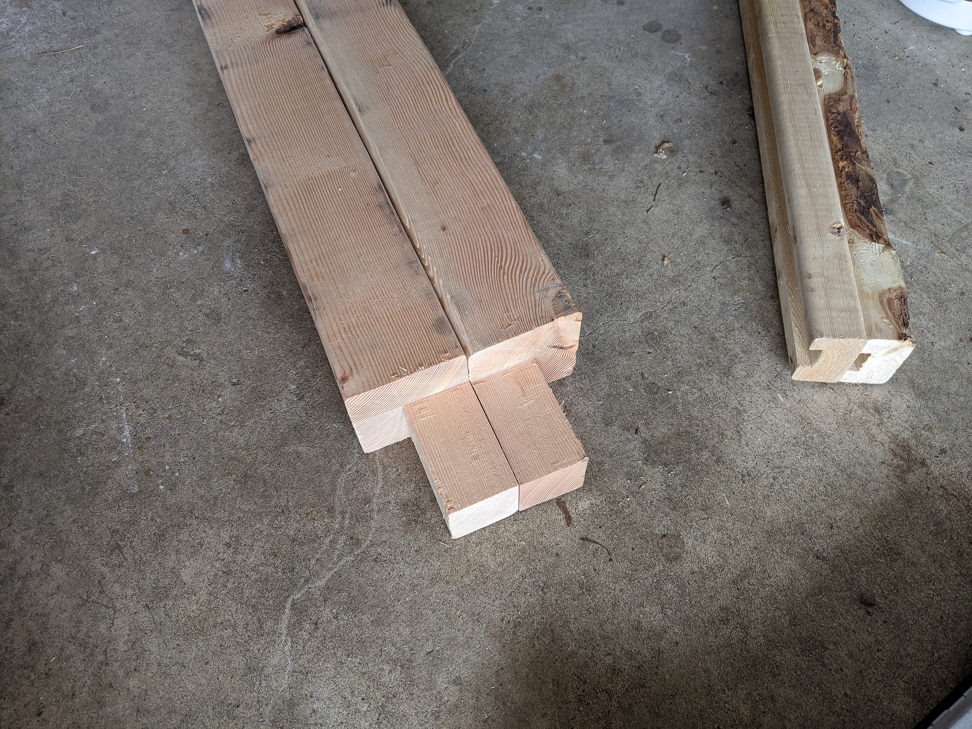
X/Z axis assembly
X/Z axis assembly

Table assembly

I started building the table right around the time of my state’s stay-at-home order. I let my local big box store select and deliver some of the worst warped, cupped, and twisted, wet wood, I’ve seen. It was still cheaper than my local lumberyards (by a lot) but quality isn’t great unless you can spend time picking through their stacks.
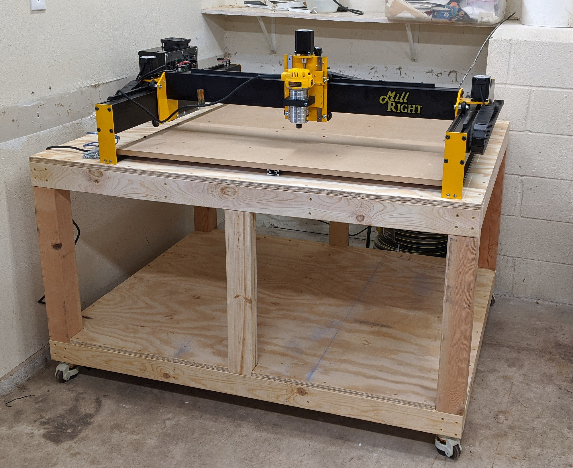
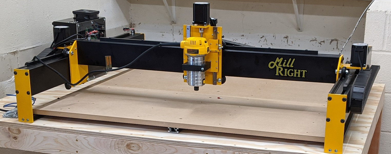
Cut 4x4s for assembly
Draw the rest of the owl
Now rolling around on casters

Mega V assembly

Assembly was easier than I expected, largely owing to the prebuilt control box. I think the longest part was just running cables through the cable chains.

There are some issues getting the Mega V set up that I (and other people) have run into, that I wish I’d known about when I started.

Instructions

At the time of building (and writing), the assembly instructions are limited to two assembly youtube videos. They’re not bad, but some sections are not clear, or slightly out of order (esp related to the endstop switches) and in general it’s a pain in the butt to watch video, pause, assemble, rewind and repeat, when written instructions with diagrams would have been easier in most cases.
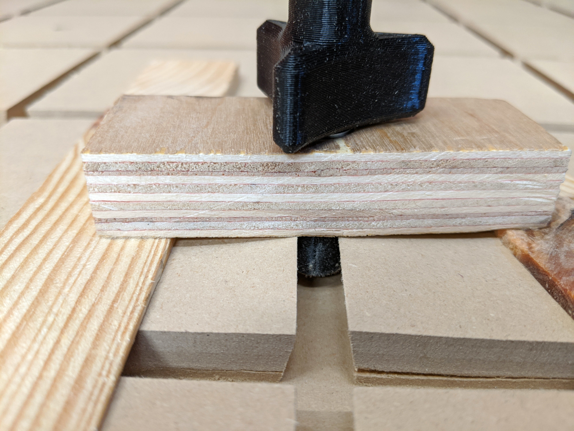
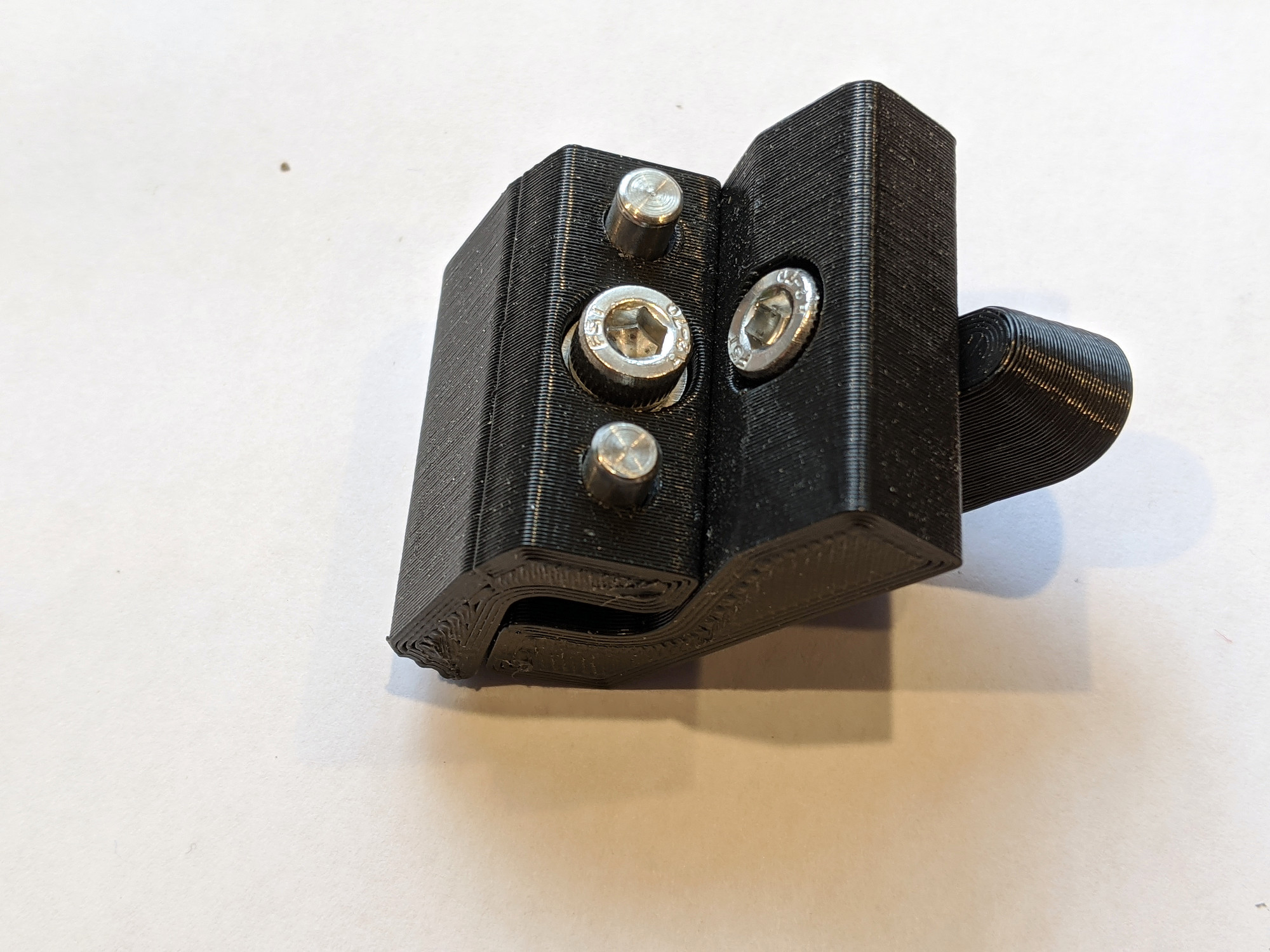
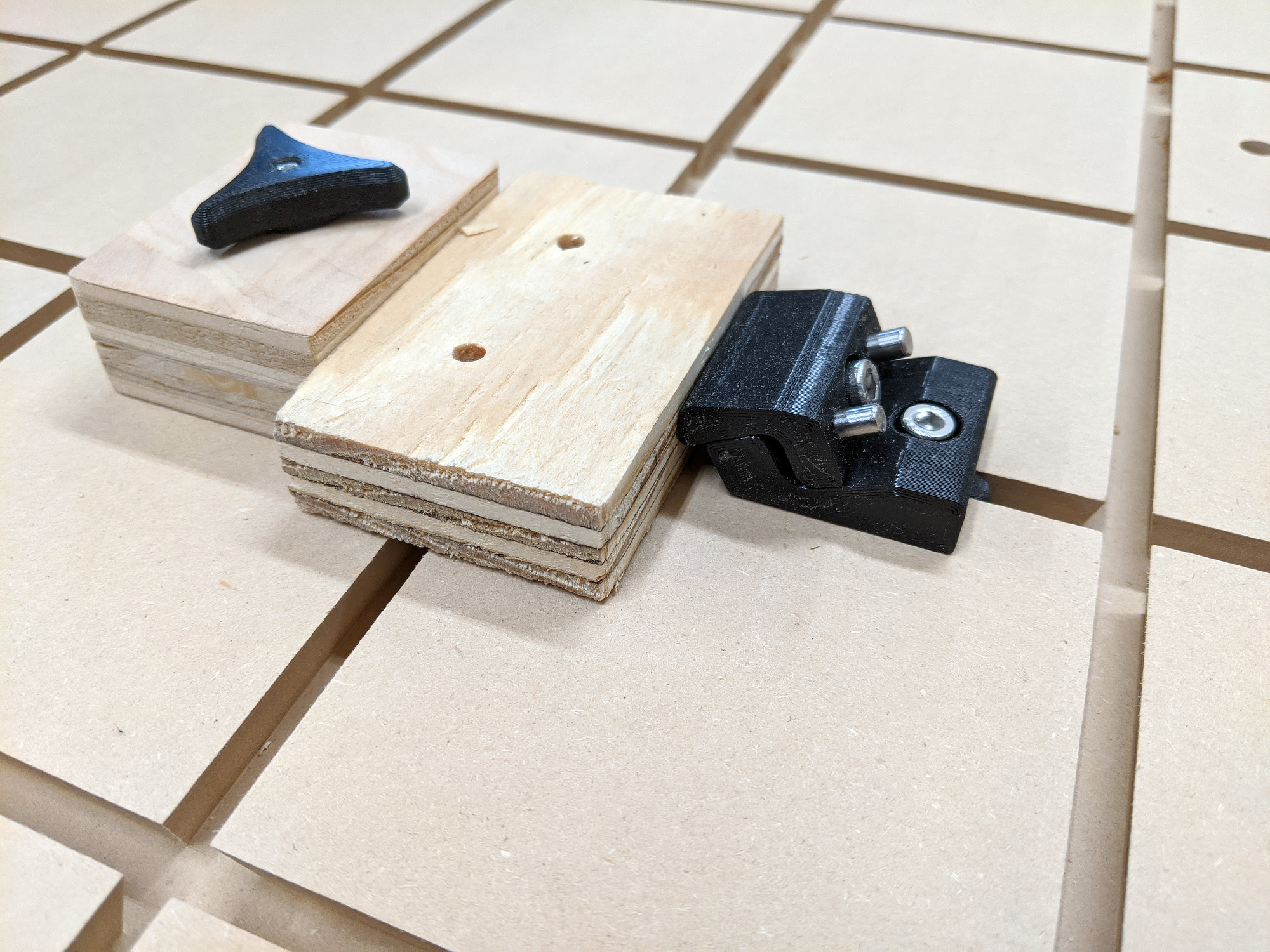
Bearing insertion

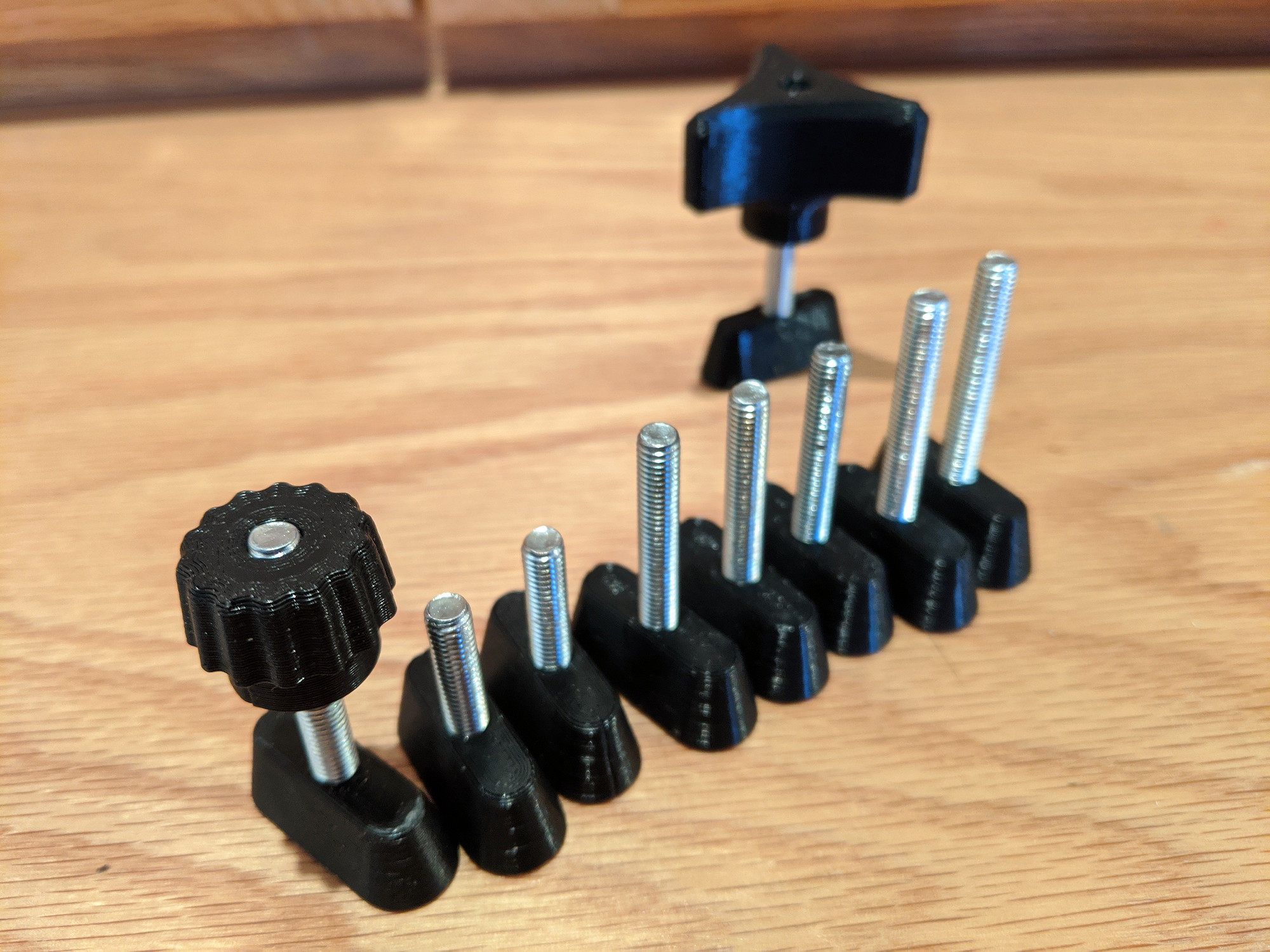
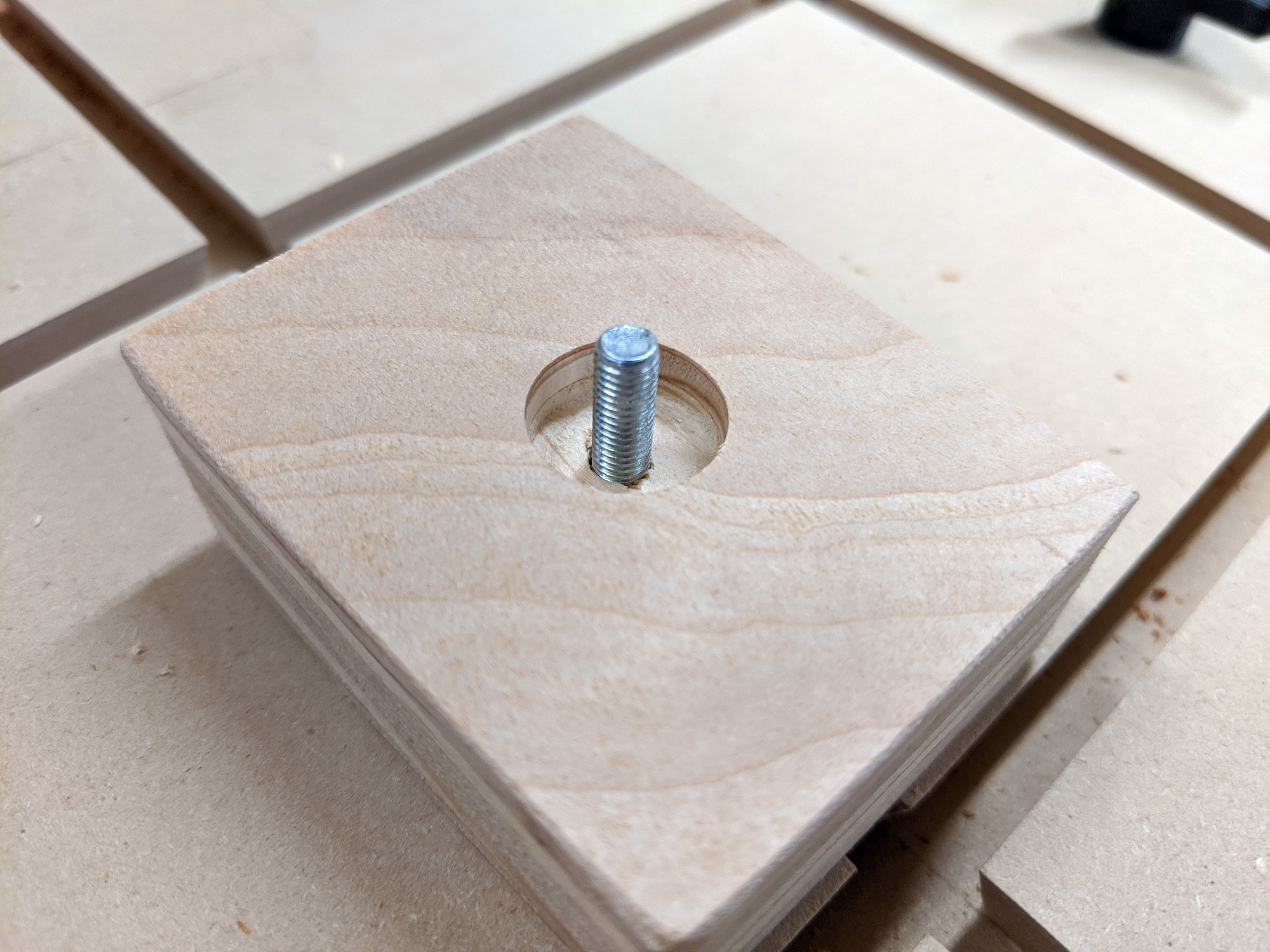
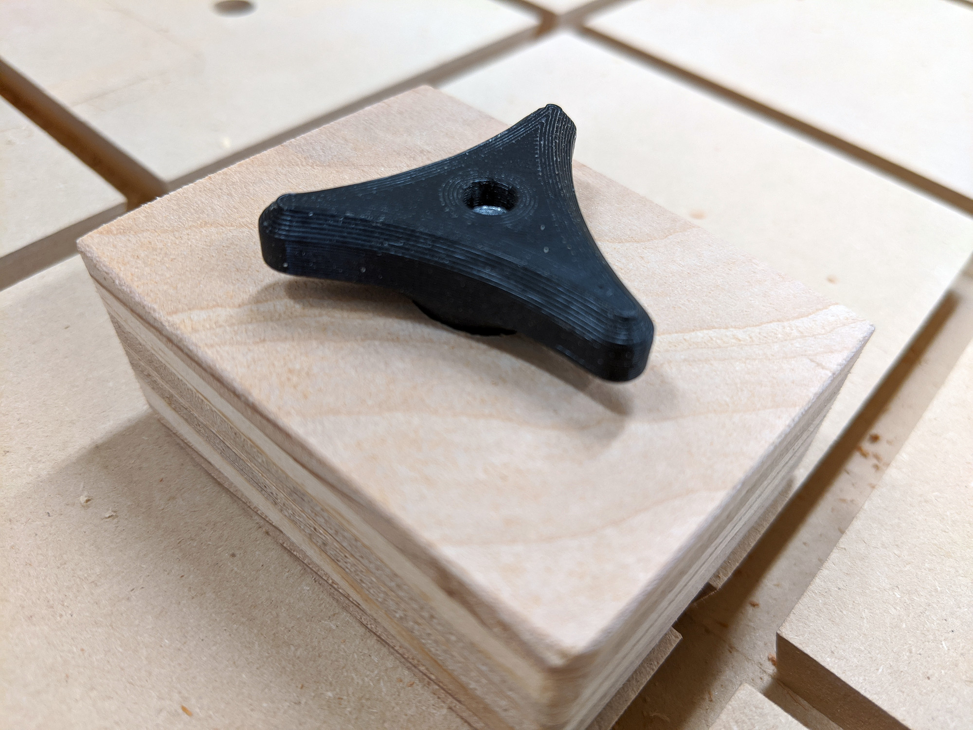
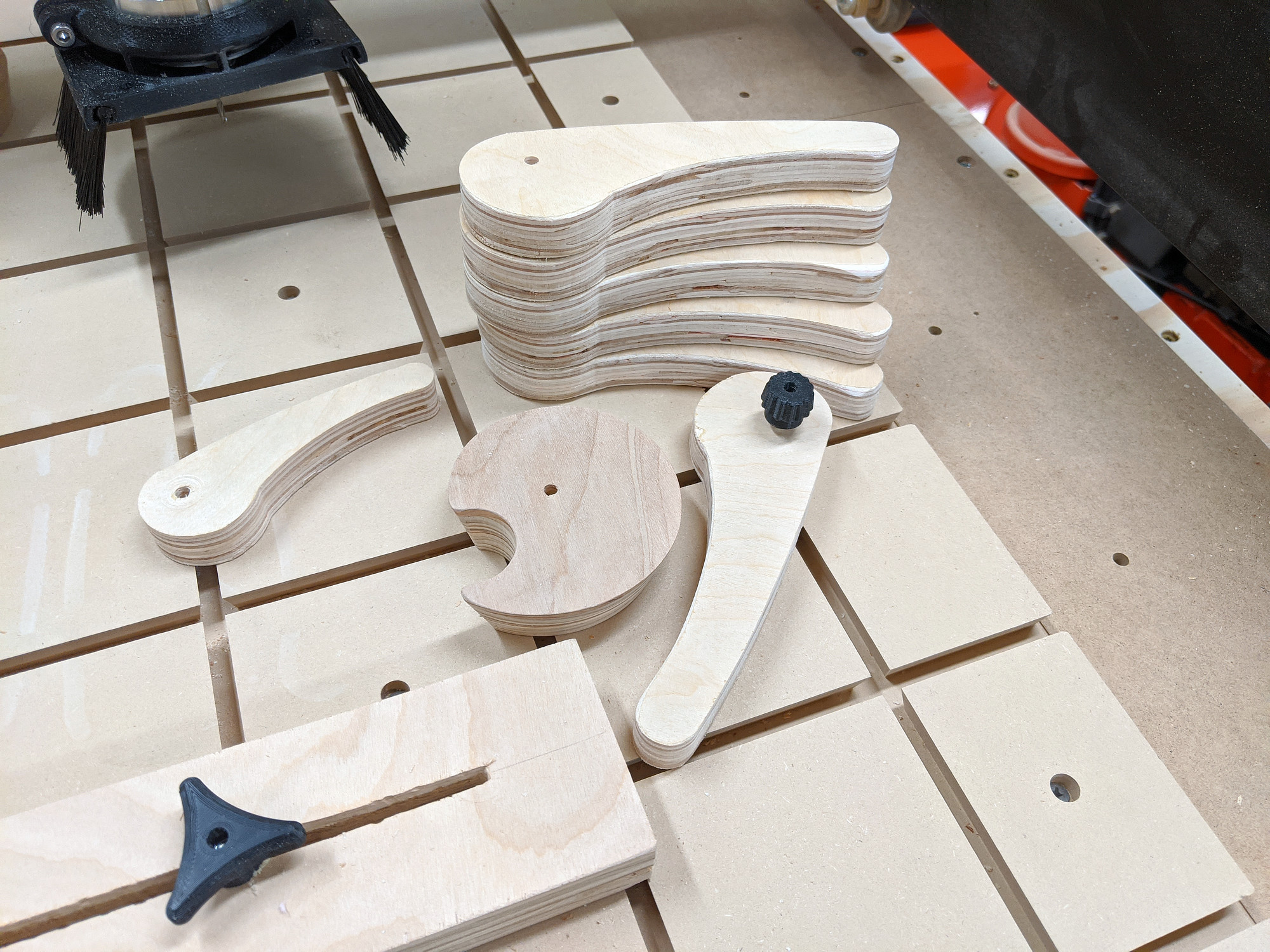
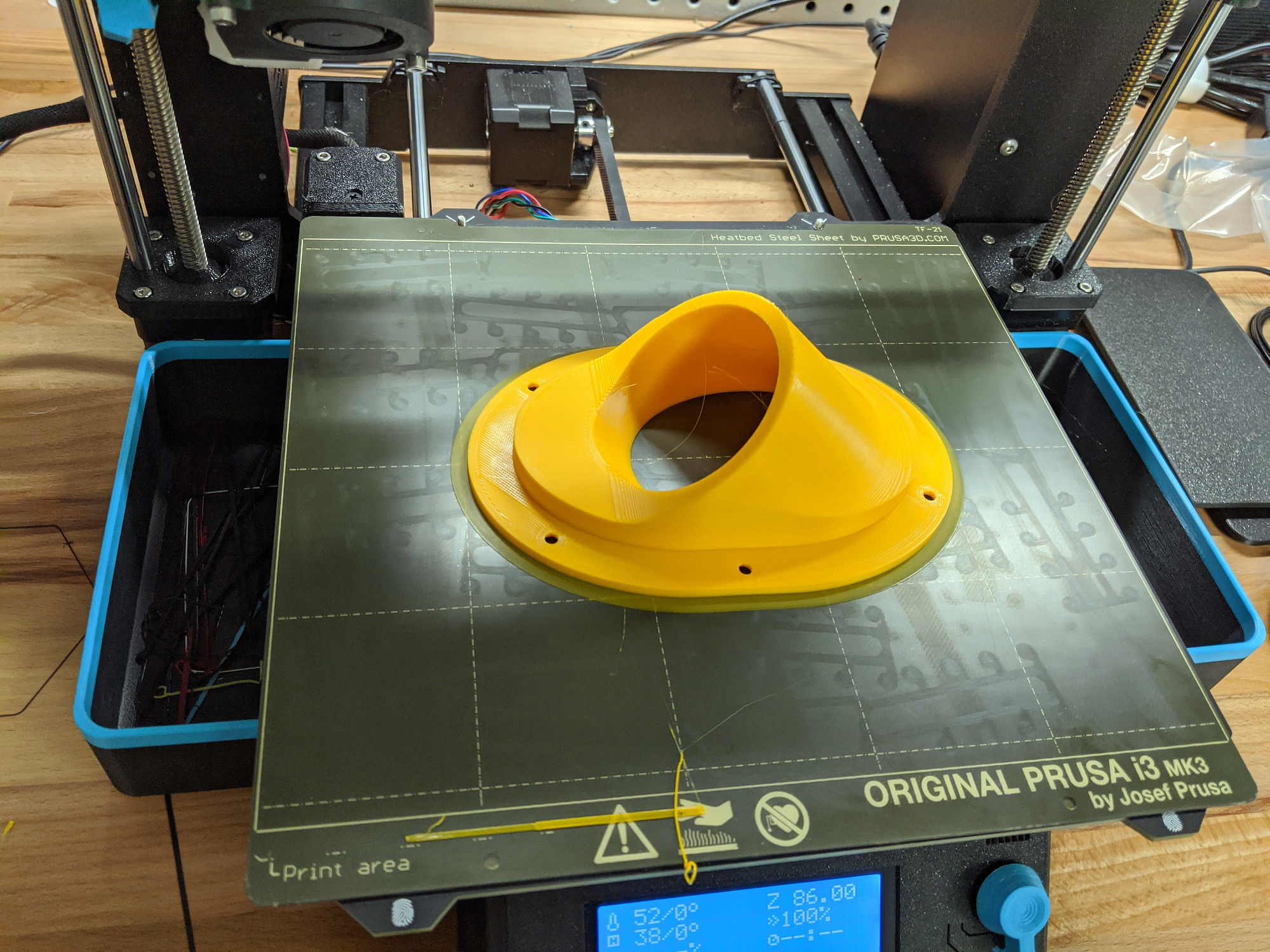
The instructions call for hammering these into the v-wheels. I found it was much easier to use this 3d-printed bearing press. I printed this ages ago, and I use it for all kinds of things now. This may be be the first time I’ve used it to press bearings into something though.
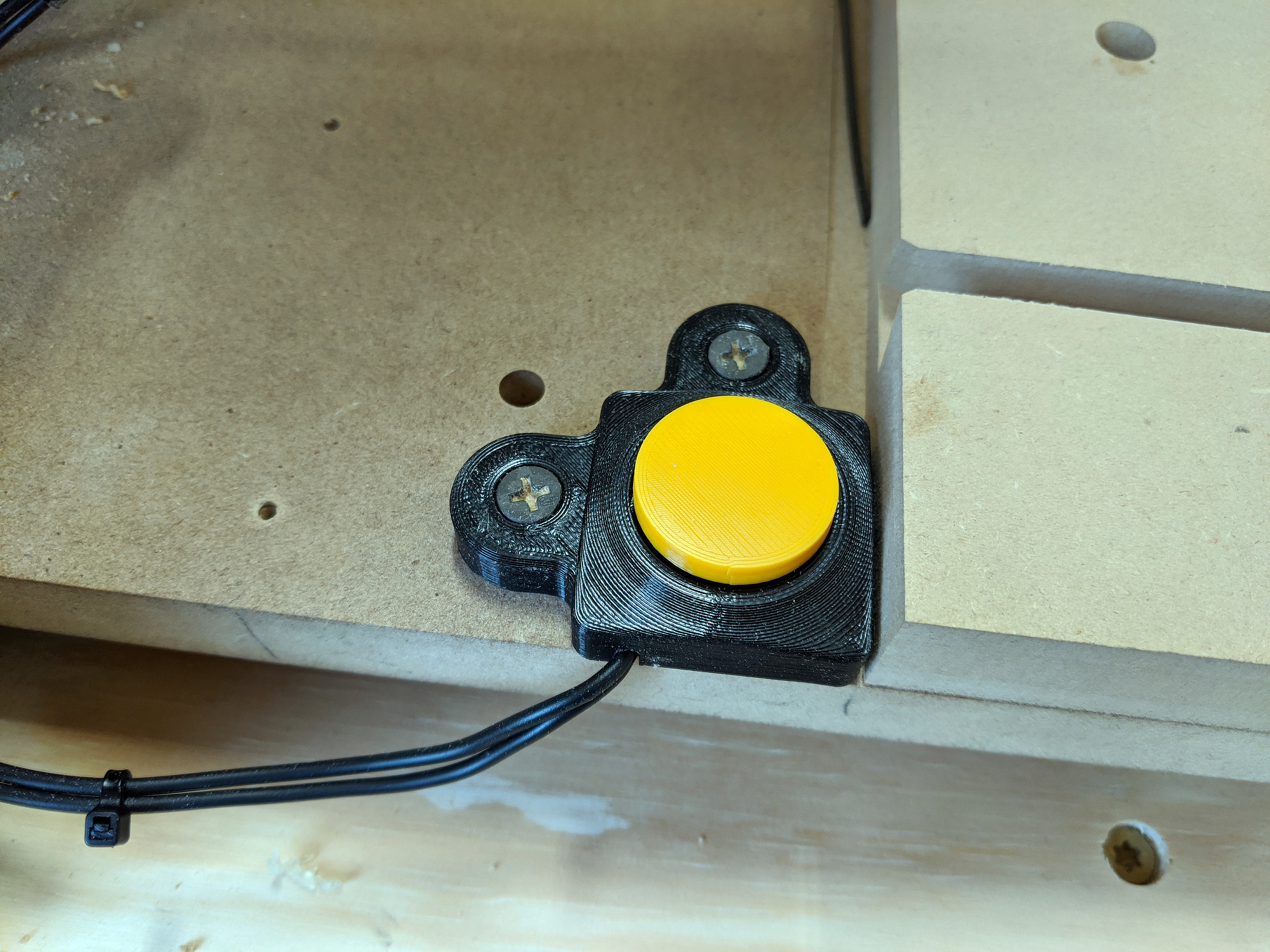
Wiring

There are a couple of issues I ran into and have seen other people mention regarding the wiring, particularly for the endstop switches. The crimped connectors are low quality and badly crimped, and the wires themselves are going to be too short to reach the control box when routed through the drag chains as instructed (at least on the 35” model).

The solution to both of these is to rewire them. I ended up running new wire for one and resoldering the aviation connector, and then just spliced an extension onto another.

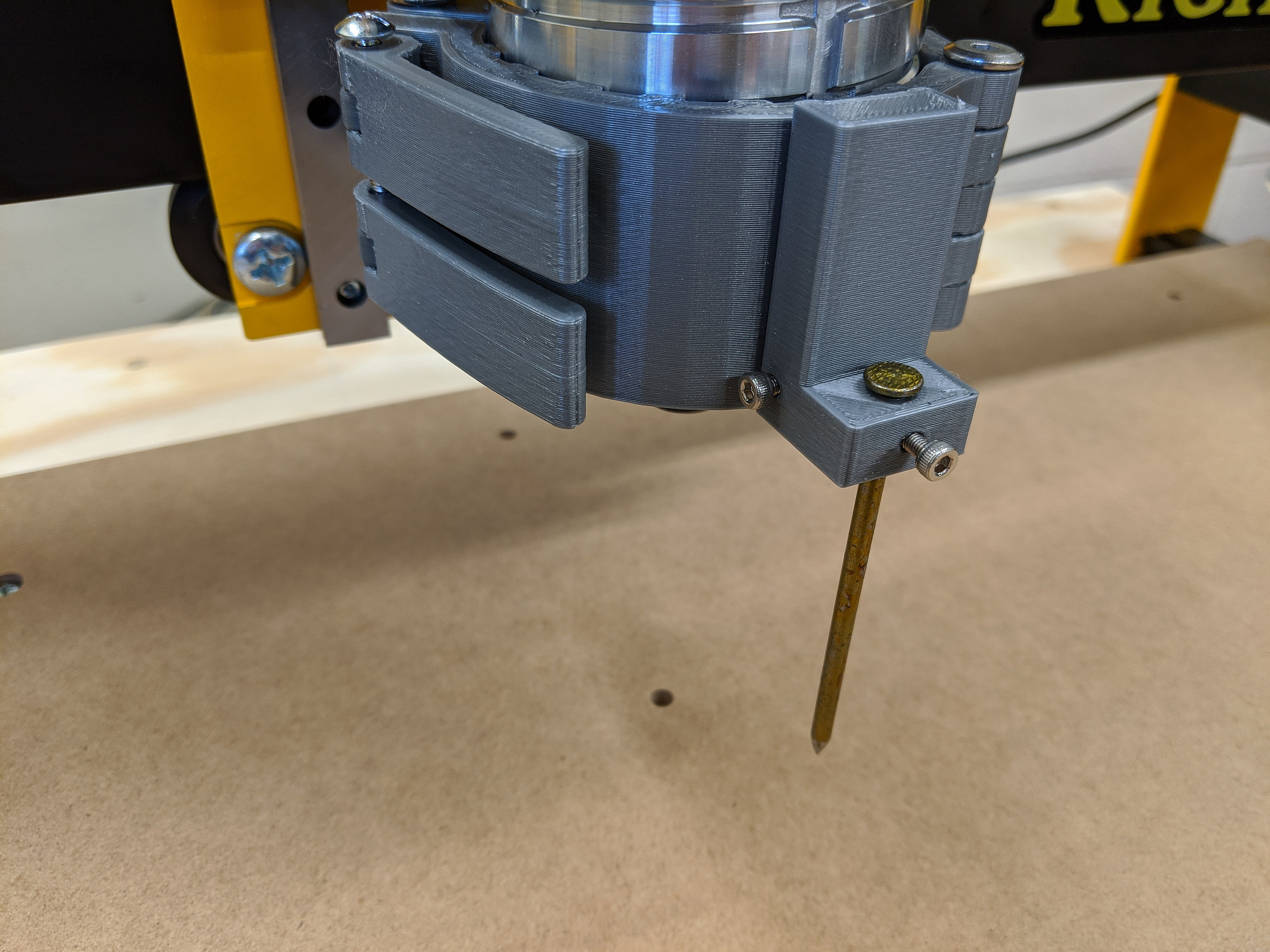
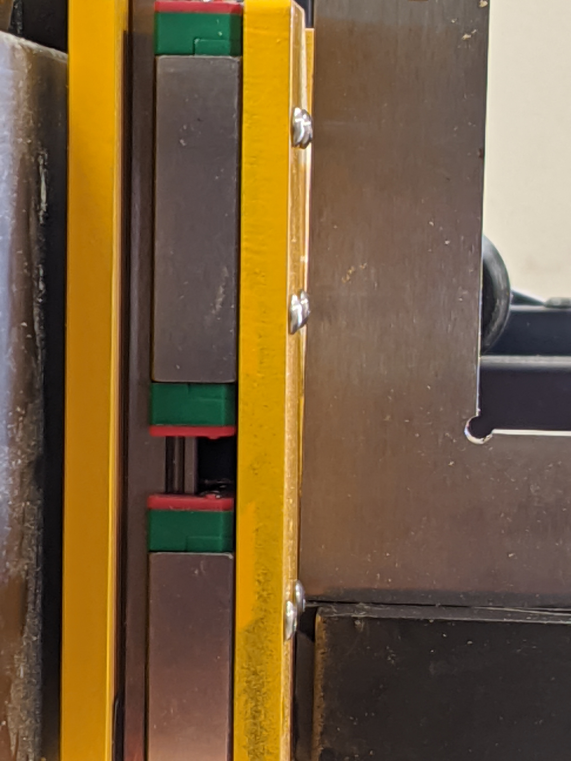
Rack and pinion meshing

This isn’t really an issue with the machine, per se, but there doesn’t seem to be a good way to determine whether the rack and pinion meshing on the X and Y axes is correct, or correct enough. It’s easy with hand pressure to warp the rack slightly where it’s fastened to the aluminum extrusion, and the gantry can lock up or miss steps.

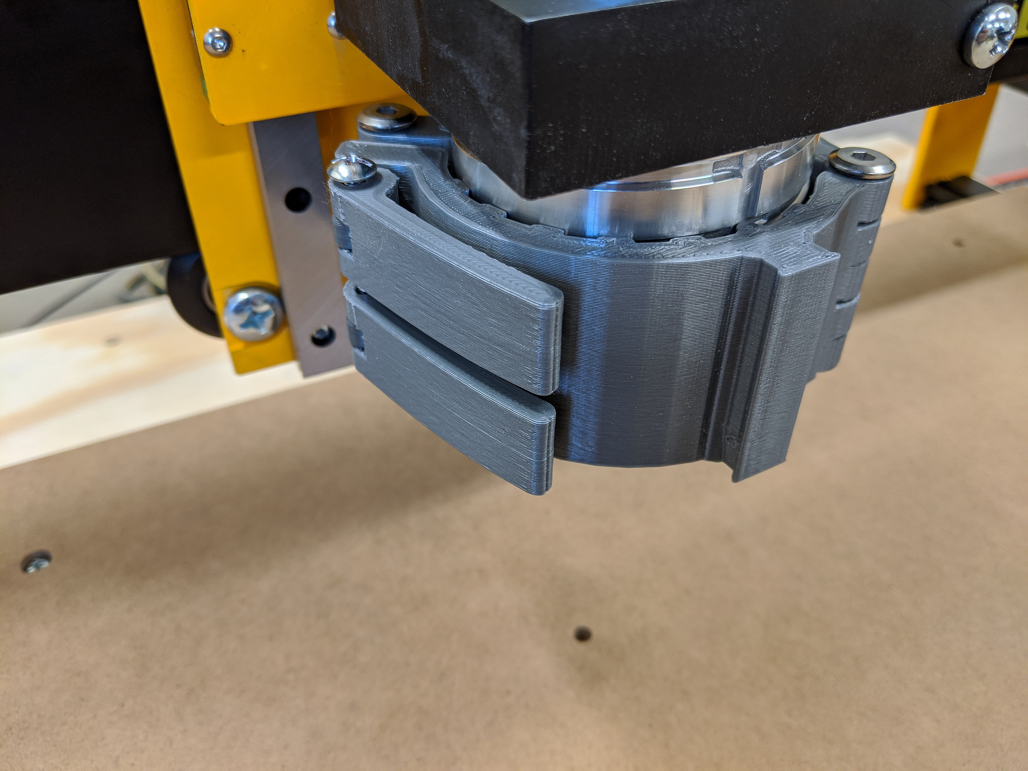
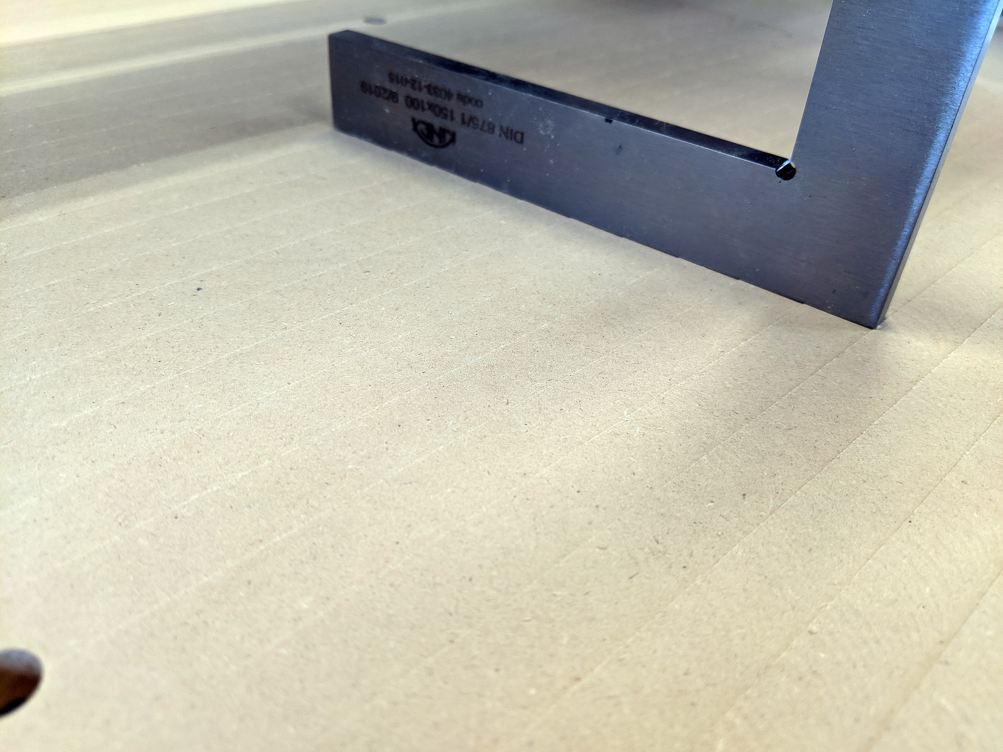
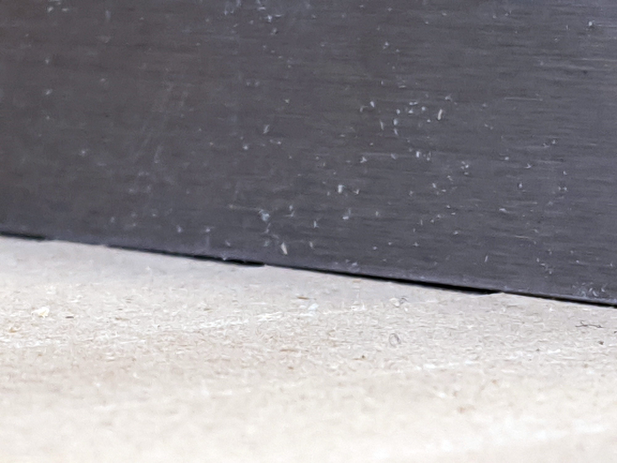
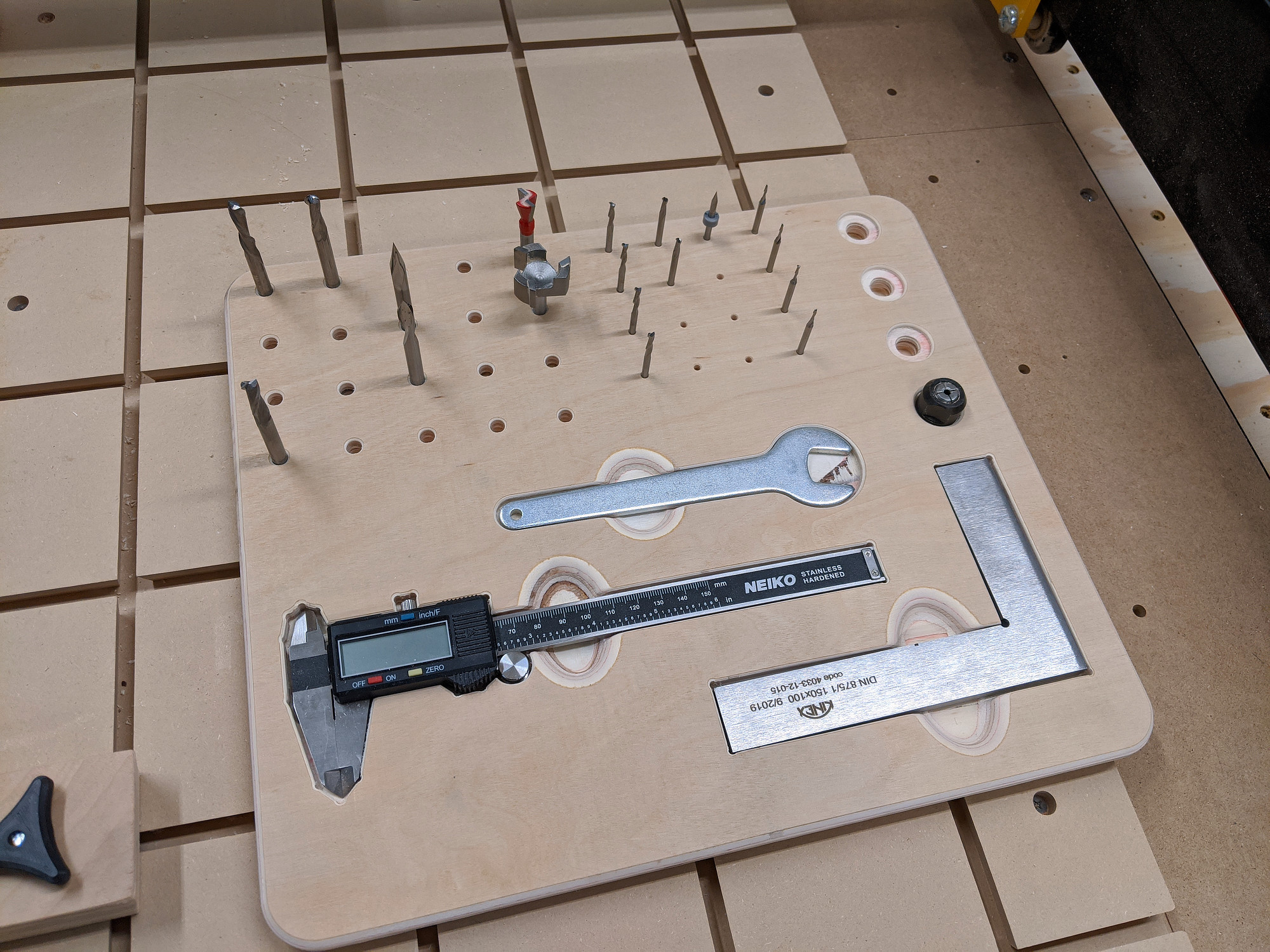
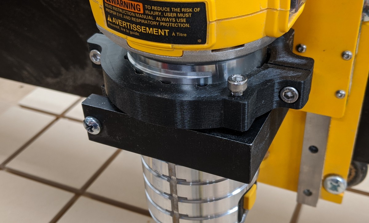
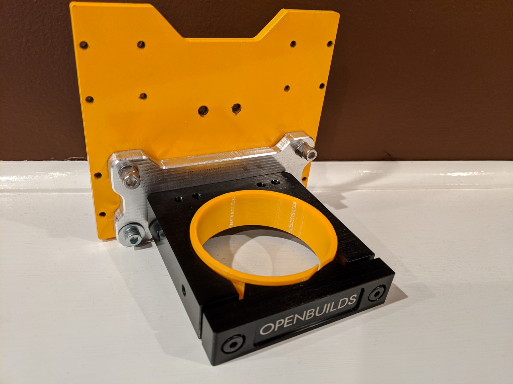
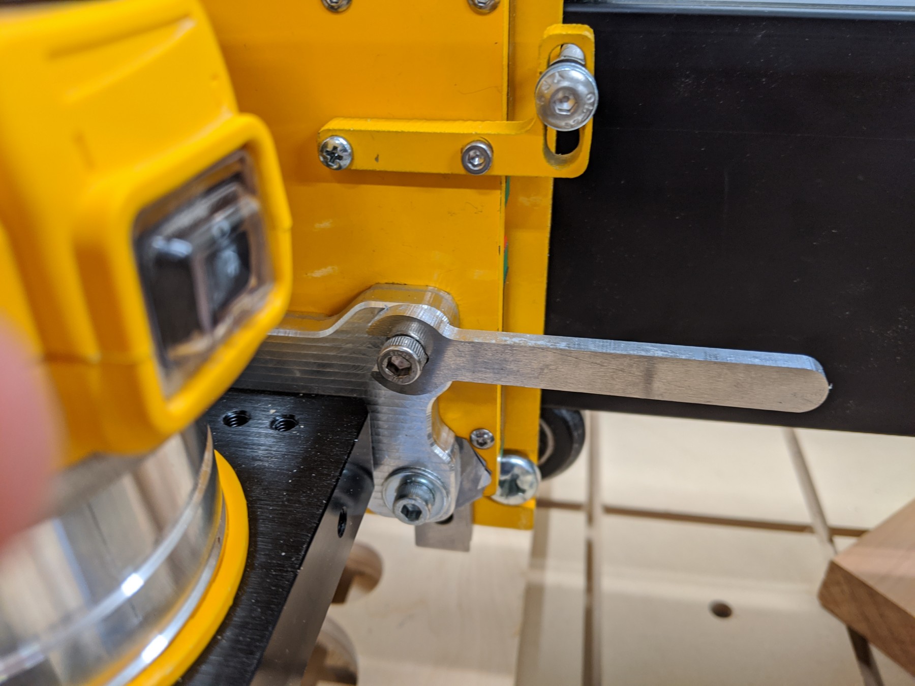
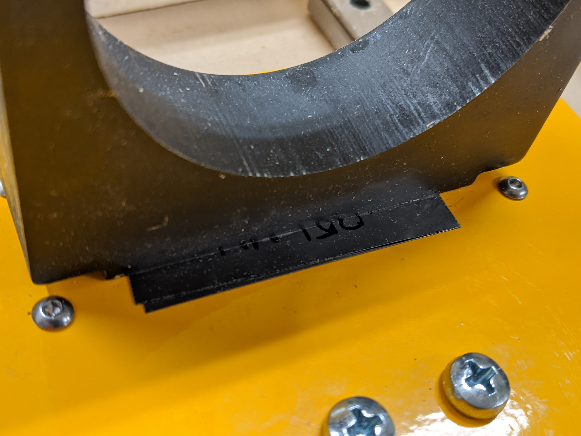
Router mount squaring

I’ve heard that the aluminum router mount is waterjet cut, instead of machined, but can’t speak to that with any confidence. What I can say is that it was somewhere in the neighborhood of 89° when I measured, causing the router to nod further forward than I could adjust anywhere else to compensate. I ended up taking apart my Z axis and shimming the mount using shim stock.

Router mount attached to Z axis plate

You can save time by getting this close to square to begin with before fully assembling the Z axis, and/or reshaping the mount where it bolts to the Z plate if you have the tooling.
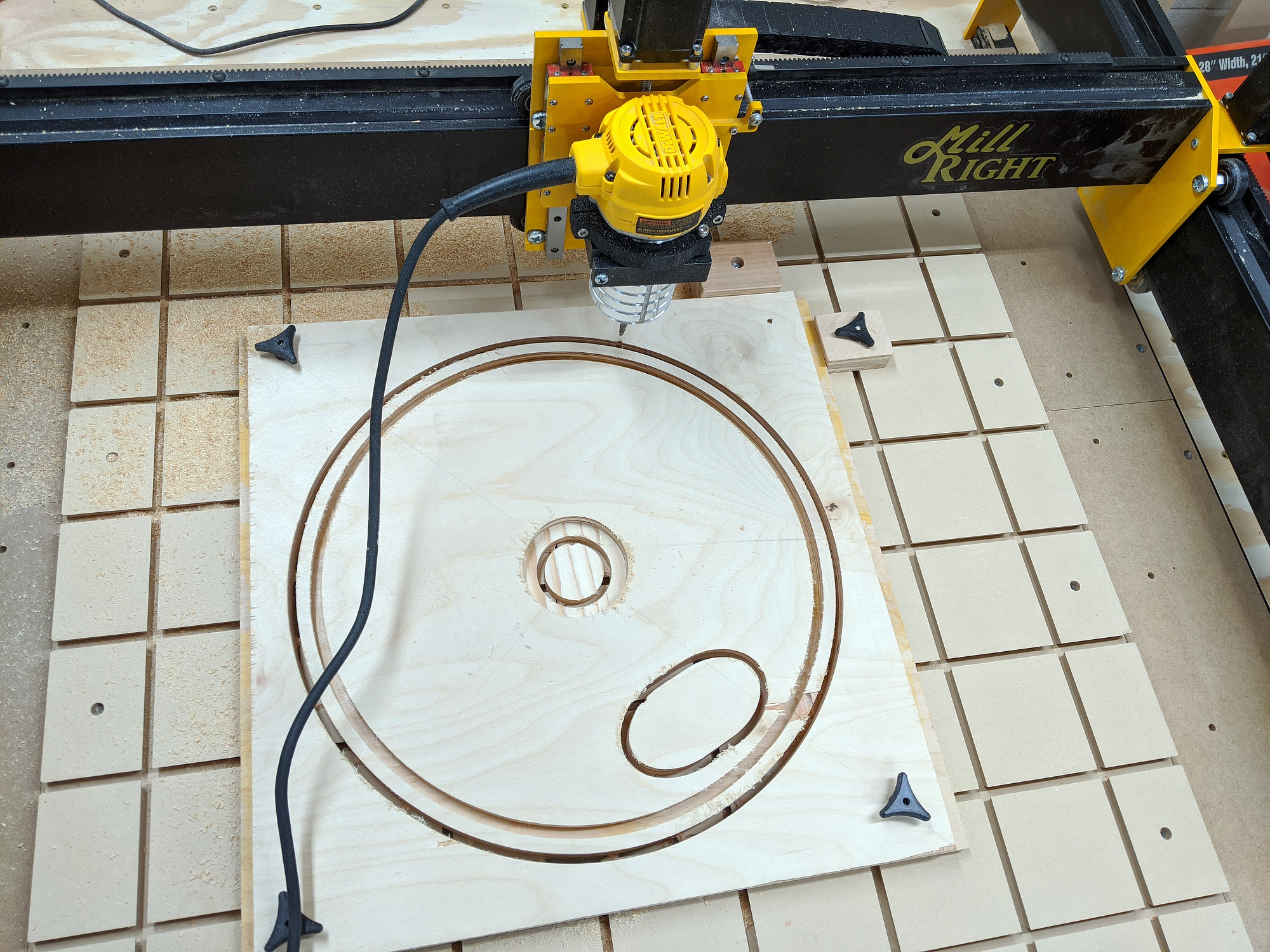
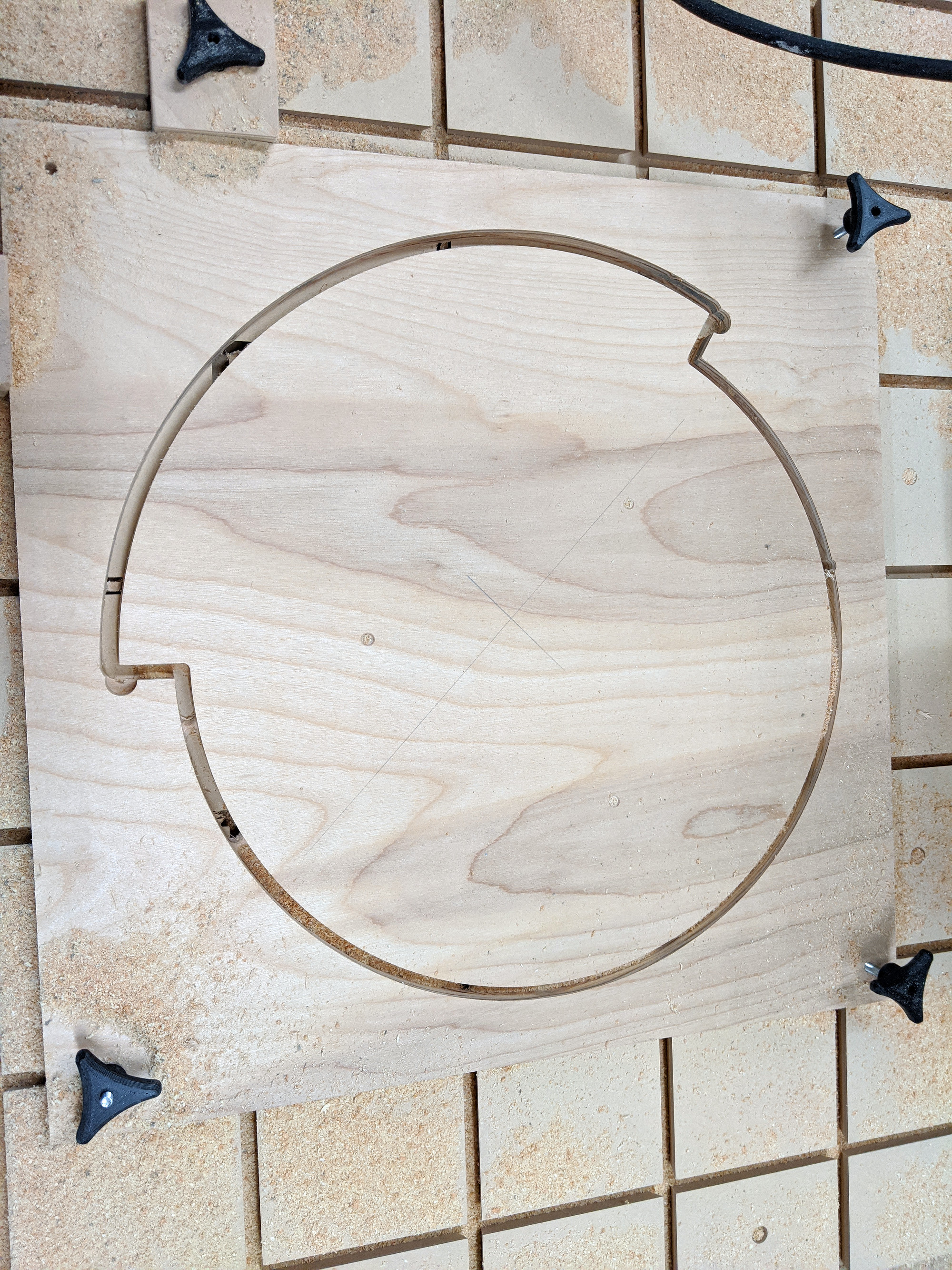
Router mount shimmed back to square

Done

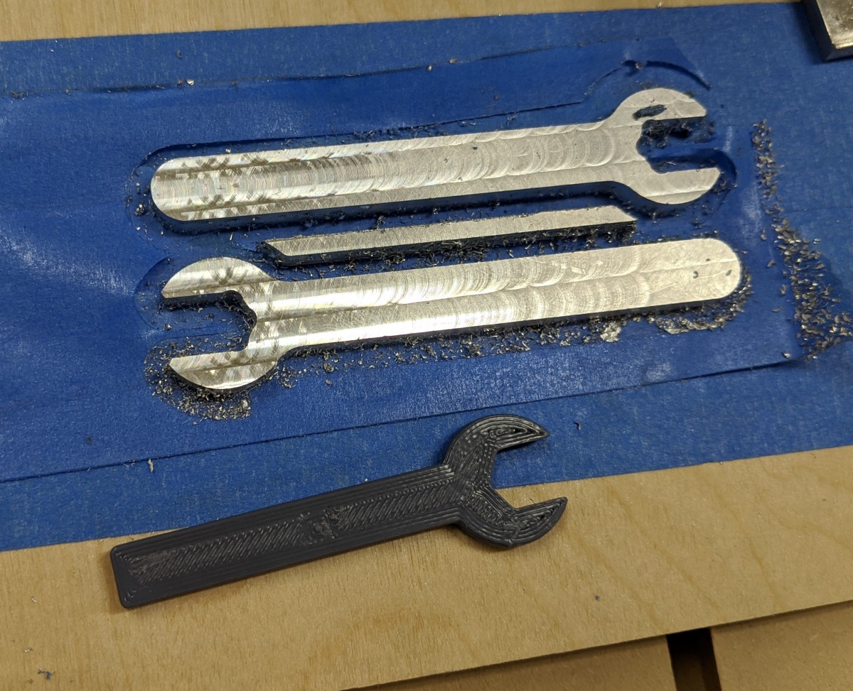
The bulk of the assembly was pretty easy, just going slowly and carefully.

Assembled
Assembled
Wiring finished also

CNC software, pen holder

After assembling the Mega V, I ordered some endmills and MDF for a supplemental wasteboard, and while waiting for those to arrive, I made a few pen holders to get a feel for the machine and sotfware.

For software, I settled on CNCjs because I had a spare raspberry pi available, and it’s open-source and easy to modify.

I’m currently connecting to it with my phone, but have tried with an old android tablet with mixed success.

For small touchscreens, this pendant interface is probably your best bet: cncjs-shopfloor-tablet. It features a simplified interface designed for touchscreens, making it harder to crash while jogging with tiny buttons (though I’ve still managed to).

Pen holders

I ziptied a sharpie to the router first. This kind of works, but since I hadn’t surfaced my spoilboard yet, and it’s a bit warped, the pen can’t follow its contours. Heres what slowly destroying a sharpie looks and sounds like.

To add a little more flexibility (and because I was still waiting for endmills), I modified a design for quick release router mount to allow for some modular attachments, and then started iterating on pen holders for it.

Router clamp
Router clamp

And here it is with a small bracket to hold a sharpened nail (I used it to measure and calibarte motor steps).

Nail holder
Nail holder

Pen holder the first

Spring pen holder
Spring pen holder

This one is very simple. It uses a collar with a set screw to keep the pen from sliding out, and a cop with a slot to hold a rubber band for tension. The pen can move up and down a bit in case of uneven surfaces, and getting the heigh zeroed out exactly isn’t critical.

Here it is running some gcode. I generated the paths for this by passing a photo to blackstripes, and then importing the SVG into Fusion 360 and then running a contour toolpath with no cut compensation.

First drawing
First drawing

This pen has a bit of a taper though, so the holes that guide it are a bit oversized, and this causes pen backlash when drawing.

Also, lots of little dots without much sideways movement prevents the ink from flowing a bit. I’d want to find a way to easily skip paths under a certain minimum distance.

Pen holder the second

To reduce some of the backlash, I used a couple of bolts with smooth shafts to guide a pen assembly up and down, without relying on the pen’s diameter. I also tried adding a bit of an angle to the pen, more in line with a natural writing angle. However, this applied a lot of friction between the bolts and the 3d printed plastic when pressing down due to the torque it applied, and the pen got stuck very easily.

Angled pen holder
Angled pen holder

Pen holder the third

I reused the sliding base for this one, but turned the pen back to straight upright, so that it can slide up and down more easily.

Vertical penholder, again

This gave the best result so far, but you can still see some of the play in the system as it “flicks” back into position at the end of each line.

Here’s a comparison of the line quality

Close up of first drawing
Close up of second drawing

Next steps

The issue with this last design is that it both relies on a tight fit between the sliding plastic carriage and the bolts, but is also hampered by any friction there. To reduce play, these holes should be as tight as possible, but then pen won’t be able to move up and down smoothly.

I’ve purchased some teeny, tiny linear rails and will attempt to replace the moving components of this last design with them instead when I get the chance.

Files

Files can be found here:


CNC spoilboard

The stock spoilerboard included with the MDF version of the Mega V uses t-nuts for workholding, but they’re pretty sparse to begin with (example here)

I knew that I wanted to add a supplemental wasteboard that could be surfaced and replaced easily, and started looking for other options.

From what I can tell, the most common options here are:

  • No special workholding: Screw, glue, nail, or even plastic pin nail in your pieces and/or workholding devices directly into the spoilboard. This means that setting up the wasteboard is easy and inexpensive, but it does suffer some extra wear.
  • T-nut and holes: Pretty easy, plenty strong, not too expensive.
  • Aluminum t-track slots: The track is fairly easy to set up, but does require some extra t-track hardware, as well as the tracks themselves. The board between the tracks can use strips, allowing better use of large material sheets.

I was planning to use aluminum t-tracks, which were only marginally more expensive than the t-nuts, but stumbled on a couple of examples of using dovetail grooves instead:

These slots have a couple of cool features. They’re cheaper (depending on what you use for fixture hardware) and allow for very dense workholding, in any direction, at any spacing.

They do have some (significant) disadvantages though, some I recognized during planning, and some only later.

Disadvantages

Tearout

When using these grooves with MDF wasteboard, you must, 100% of the time, use clamps which press directly against the wasteboard surface at the clamping point, or the MDF can absolutely shear out. I was easily able to tear out an entire 4” square section by hand with the clamping pressure spread away from the slot. This eliminates many of the most common types of clamps.

Dovetail tearout
Dovetail tearout

Available space

I’ve reduced my available space a few ways with this board. First, by putting another 3/4” board on top of the existing wasteboard, I’ve lost a pretty good chuck of my machinable Z height. I’m already planning a new stock and secondary wasteboard to reduce the height.

In order to route the slots with the CNC itself, using a 1/2” dovetail bit, I needed a little clearance on all sides for the bit to enter and exit the edge of the board, so this reduced my X and Y range as well.

Lastly, I wanted the router to overhang the end of my spoilboard a bit so that I can (hopefully) cut dovetails in upright stock, so I slid both spoilboards back a couple of inches, which reduces the Y range a little more.

Resurfacing

I have a bit of extra room, but I’m limited it how many times, and how deeply I can resurface my wasteboard before the inserts no longer fit correctly. I can reprint them easily when that happens though.

Ease of use

While these can be easy to set up, they rely on a pretty good fit inside the slot. This means, though, that they’re harder to get in and out when the slots fill up with chips.

They get stuck

More on this later, still trying to figure it out, but I often have to unjam these from the slots after use.

First attempt (spoiler)

First, I cut a section of MDF, a bit oversized, and temporarily fastened it to my wasteboard using drywall screws around the outside edge. I really want to find a better fastener for this but haven’t yet.

Then, I set up some operations in Fusion 360. First, I surfaced the area of the wasteboard that the CNC could reach, enough to take care of any real high spots and/or warping. This also showed just how out of tram my router was, with a huge nod forward. After some investigating, most of this nod was coming from badly off-square router mount. Once that was shimmed back to square, there was enough play at the router to get it close to trammed using a simple tramming tool.

Before tramming
Before tramming
Before tramming, close up

Then, using a 90 degree chamfer bit, I made some spot markings for the holes that would fasten the new spoilboard to the stock one.

These I then hand drilled, deeply countersunk, dropped some CA glue into for a little more longevity, and finally fastened down.

I then ran a 2D contour toolpath to cut the excess MDF free and removed the temporary screws.

Wasteboard cut out, drilled and fastened

After the wasteboard was fastened and cut free, I made some relief cuts for the dovetails just under the final depth with a 1/4” downcut endmill, and then ran the dovetails in the same slots.

Wasteboard with dovetail grooves

Here I had some trouble, and had to start over.

First, with the relief cuts and dovetails, the MDF wanted very badly to curl up. Some of my screws were around 5” from the edge of the board, and that was enough for it to want to lift.

Wasteboard lifting
Wasteboard lifting

Secondly, somewhere along the way, I lost some steps in the Y direction, and a couple of my dovetail slots were both the wrong shape and size (due to them not being centered on the relief cuts).

Off-position dovetail

Second attempt

I went back to fusion and moved the screw holes around. I increased the density of the screws, and made sure they were fastened close to the edge as well.

Since the process of manually drilling these was such a pain, I also set up a toolpath to bore these down to final depth instead of just marking them, leaving me to only need to countersink, drill, CA glue, and screw each of them, which was still a pain, but one step fewer.

Finished pass 2, way more screws

Afterward, I ran through the same steps as before. I’m not sure when the missed steps happened. Maybe I crashed something. At any rate, I didn’t end up with any missed steps for the second attempt.

I also took the time to set up an extra toolpath to cut beveled openings in all of the slots. It was really satisfying to see these run successfully.


CNC workholding

After finishing the dovetail grooves, I started on workholding and clamps by designing and 3d printing some dovetail inserts and knobs.

Dovetail fittings and knobs

Dovetail inserts and knobs

I tried a few different bolts, but settled on 40 and 50mm M5 hex bolts. Any longer, and I have trouble clearing them with my router (and extra spoilboard).

For clamping taller blocks, I can counterbore them to recess the clamping knobs into the material a bit, and this helps keep the clearance height down a bit.

Clamping block with counterbored hole
Knob recessed into block surface

The inserts and knobs went through a few iterations.

The inserts got a little smaller in width, so that they can slide in the dovetail grooves more easily, and a deliberately undersized nut diameter so that the bolt heads fit tightly in them, instead of being easily pressed in.

Most recently, I also made them a little bit shorter, so that I can surface the spoilboard a few times, but also to make sure that when clamping they don’t press directly against whatever it is I’m clamping, causing them to slide even when clamped tightly.

These are not perfect though. With tight clamping, these get stuck in the MDF. I’m not sure if the MDF is getting deformed and snapping back when pressure is removed, or if the layer lines in the 3d print are kind of biting into the MDF surface, or if they’re getting jammed by rotation.

After clamping tightly, I usually have to uncscrew the knobs, pull off the blocks or cam clamps, and then poke the inserts back into the slots with a screwdriver to free them up. I’m not sure how to solve this yet. I’ve tried a few variations so far.

  • Sanding and polishing the inserts so that layer lines are soft and smooth
  • Increasing the taper of the inserts, so that they’re tighter toward the bottom of the slots
  • Rounding the top of the inserts so that the edges are less likely to gouge in
  • Adding reliefs in the sides at 10 and 4 o’clock, so that they’re less likely to get jammed by rotation.

I haven’t notice any difference with these though.

Stop blocks

I started by just drilling 5mm holes in random bits of scrap wood. This works fine with enough lateral and downward pressure but quickly realized they work much better if they’re a little taller than the material being clamped, and also have a slight 15° bevel on them to help keep the material down. Seems obvious in retrospect.

These I just cut on a table saw, and then drilled a hole roughly in the center.

Cam clamps

These are simple spiral-shaped cam clamps that apply sideways pressure, but won’t hold anything down.

I cut these from 3/4” plywood, and they work great.

Clamps all cut out and drilled

Round cam

The above picture also has my first pass at a round cam clamp, cut from scrap redwood. This one is one inch thick and has the same 15° bevel on it to help hold work down. Before cutting it, I drilled two holes through it surface and held it in place with flange nuts rather than clamping.

This was roughed with a 1/4” square endmill, and then finished with fine passes with a 1/4” ball endmill. This could have been made much easier and faster without the CNC, using a bandsaw and an a tall bevel bit, but I don’t have either.

Here’s what it looks like in use.

Spiral cam holding a block

I refined the shape a bit, so that it has a smooth spiral from beginning to end, instead of having some lost space around the perimeter that can’t be used for clamping, and cut a new one from 1” plywood (really two 1/2” sheets sandwiched together).

Instead of bolting through it, I modeled tabs for it manually in Fusion.

Round cam after routing
After removing from the sheet

Low profile clamp

One issue I’m having with these styles of clamp is that they have to be taller than whatever I’m working on to have any holding power (at least downwards).

I’m experimenting with low profile sliding clamps, and just finished designing and assembling this one (a rebuild of one I found on thingiverse to fit my hardware).

Low profile clamp, printed
Clamp in use
Clamp in use

This uses a M5 18mm socket screw (I’m really using a 16mm but it’s a little short) for the sliding part, a M5 16mm screw to hold it to the dovetail insert, and a couple of 5x25mm steel dowel pins.

It holds fairly well, but I haven’t tested it thoroughly yet. It may not be better than any other side clamp, especially since the “teeth” are quite dull.

Files and downloads:


CNC software and jogging

To drive the CNC, I’m currently using CNCjs, installed on a Raspberry Pi 3b+.

The system is currently headless, because I don’t have a dedicated laptop for it, and my CNC lives in my garage where it’s too cold to leave an LCD screen.

CNCjs is fine, and a good fit for this use case, but pretty clunky on a small screen, and lacks some of the features available in other gcode senders, like autoleveling, basic gcode generation for simple operations like facing, cancelable jogging, angle deviation probing…

I find jogging via the default web interface really uncomfortable. It’s very easy to hit the wrong button among the tightly packed buttons, and do something bad, like rapid moving to zero when things are in the way. I’d like to say I only did this once, but…

The other issue with jogging like this, particularly with a small screen is that button presses may be queued, and delayed, and then may execute in series unexpectedly. There’s also no real way to quickly cancel dangerous moves.

I saved myself some pain by enabling soft limits in GRBL, but I need to tune these better.

For small screen use, there’s a much better interface at https://github.com/cncjs/cncjs-shopfloor-tablet, which I used for a little bit. It too has some issues; It’s much better suited to a tablet display than a phone, and you cannot run macros from it.

I started down the path of making the interface more responsive, but stopped using it before finishing.

I also ran into this issue which drove me crazy for a few days before discovering that, if I left the interface open on my phone, and the phone went to sleep, whatever job was running would halt.

File uploading

To transfer gcode from my machine to the raspberry pi, I’m currently using https://github.com/efeiefei/node-file-manager to upload the gcode to the CNCjs watch folder. It would have been easy to set up network shares for this also.

I’ve also written (hacked together) a utility to upload gcode files to node file manager, as well as opening them in my default editor, and have set this utility as my Fusion 360 editor.

Now, these are automatically uploaded after post processing.

Utility can be found here: https://github.com/Billiam/upload-passthrough

Probing and other macros

I’m using a few macros right now.

One for XYZ probing using a touchplate, as well as two for a bitsetter are from here: https://github.com/cncjs/CNCjs-Macros

I duplicated the XYZ probe one and deleted a bunch of it to act as a Z-only probe, since I’ve been setting the Z-zero to my spoilboard away from my material, when I do full through cuts.

I’m also using one from this page to jog around the X/Y perimeter of loaded gcode: https://github.com/cncjs/cncjs/wiki/User-Guide

Jogging improvements

I dug up a wireless keyboard I’d forgotten about, the Logitech K400+.

I found this module for CNCjs which allows jogging with a wireless keyboard: https://github.com/cncjs/cncjs-pendant-keyboard, but I don’t have that specific one, and some of its special key mapping didn’t translate to mine.

I also found this one which supports smooth jogging while holding a key, as well as grbl jog cancelling. https://github.com/jheyman/shapeoko/tree/master/cncjs-pendant-keyboardreader

This one is more generic, but can’t work with my headless setup, as it requires the running application to maintain focus.

I’ve forked it here: https://github.com/Billiam/cncjs-pendant-keyboardreader

It now uses node-hid like cncjs-pendant-keyboard so it doesn’t require focus, and works with the Logitech K400 plus.

I have it set up to jog on X and Y with the arrow keys, Z axis via I and K in 0.1mm increments.

Ctrl + direction will move 10mm at a time.
Alt + direction will move 1mm at a time.
Shift + direction will move continuously in that direction until shift is released.

Ctrl + H will home the machine.

I’ve also added a few macros via keyboard:

Ctrl + P will run an XYZ probe
Ctrl + Z will just run a Z probe
Ctrl + 1 will initialize the bitsetter for the first tool
Ctrl + 2 will use the bitsetter for tool changes
Ctrl + Shift + Return will continue after pausing for toolchanges.

With an easier setup for jogging, I’m only using the default CNCjs interface on my phone to start jobs.

Eventually, I’d like to replace the keyboard with something more specialized, but most of the commercial ones I’ve seen aren’t compatible with GRBL.


CNC tool setter

I had some keyboard switches left over from a previous project, and wanted a more convenient process for changing bits during a job.

Bit setter mountet to wasteboard

This is a simple switch, wired in parallel with my touch plate, that is used before and after changing router bits.

When changing a bit, a macro offsets the Z height by the difference between the first and second tool length, and work can continue with the new bit.

This process is much faster than manual zeroing after changing bits, or using the touch plate. The tool can overshoot the switch’s trigger position slightly without damage, so the probe speed can be much faster than a touch plate, and it doesn’t require connecting the probe clip.

Additionally, if the original zero position has been carved away by the previous job, the tool setter can still be used.

It’s promising, but has some issues.

First, it has moving parts exposed to cnc dust and chips. I added a magnetic cover for it to help with that

Second, though it’s much lower profile than commercial options, it’s just about flush with the surface of my wasteboard. For surfacing, when I’m cutting off the edge, I’ve been pulling the cap off and taping it down. I’m planning to move it out in front of the wasteboard instead.

Third, repeatability isn’t amazing (around 0.02-0.04mm) because the 3d-printed button top I’m using isn’t a perfect fit on the switch, and the switch has some play as well. I’m looking to replace it with something with less play, but haven’t found the right thing yet.

3D printable files for it can be found here


This is my first real CNC project, a cyclone dust separator.

There are lots of different versions of these floating around, but most use big box store five-gallon buckets, or larger garbage cans, but I wanted one that would fit comfortably underneath my CNC table and still have some capacity.

I settled on using a short, 10 gallon steel bucket

The lid and is made of 1” plywood, cut with a 1/4” endmill and a 90 degree chamfer bit. The baffle just redirects airflow, so only uses 1/2” plywood. It was also cut with a 1/4” endmill, but the extended section that contacts the wall of the bucket was tapered with a 1/4” ball end mill to match the slope of the bucket.

Lid after cutting on the CNC
Baffle profile cut
Baffle profile cut
After trimming off tabs on the router table

I’m using readily available schedule 40, 2” PVC pipes and fittings and 3d-printed this fitting to allow the pipe to pass through the lid at a 45° angle.

3D printed fitting
3D printed fitting

I installed the fitting using wood screws and caulk to seal it, and added a bead of caulk in the lip and smoothed it down. It kind of works, but a softer silicone caulk would have worked better.

3D printed fitting
3D printed fitting

I held the lid and baffle together with dowels, screwed in from the top and bottom. Here’s the assembled lid with baffle (upside down).

Lid assembled
Lid assembled
Fully assembled separator

To connect the separator to my shopvac and hoses, I used 2” PVC, heated (agonizingly slowly) with a (tiny) heatgun until they could be formed over my hose fittings.

PVC vacuum hose adapter

It works well, but I haven’t measured its efficiency. I’m not really seeing anything in the shopvac now though.

Success
Success

CNC toolholders

While working on some other projects, I mocked these guys up real quick to help organize some of the tools and accessories I’m using with my CNC right now.

The design is simple, and they’re just carved in scrap 3/4” plywood, so recreating them if when tools change won’t be a big deal.

Eventually, I’m planning to have these in drawers instead, but it’s a good start.

Tool holder
Tool holder
Workholder holder
Workholder holder

To make an accurate profile for complex (mostly two-dimensional) parts, I took a photo zoomed in at a distance (to minimize perspective distortion), with a ruler visible.

This photo can be imported into Fusion 360 as a canvas, and the ruler used to calibrate it.


CNC tramming plate

Note: This is an older (2+ years old) project, and there are now better third party options available (check Millright groups on facebook), even completely replacing both the Z plate and router mount with significantly beefier aluminum parts free of these issues.

There are a couple of problems with the default router mount on this CNC.

The first is that none of its sides are parallel. When mounted to the Z-axis plate, it visibly dives downward in the front toward the spoilboard.

The surfaces that contact the router are also tapered inward, so any adjustment to the router clamping has a tendency to shift the router in one direction or another.

Both of these issues can be shimmed (somewhat), but since the router mount bolts through the Z plate from behind, it takes a lot of work to disassemble the Z axis, loosen the router mount, shim behind it, tighten back up, and reassemble before checking tram again.

The first pass I made at fixing this used a 3d-printed collar, positioned above the router mount with a few adjustable screws to adjust the offset. The idea was that the collar could be tightly fastened to the router, adjusted, and held down firmly while tightening the router mount’s clamp to make fine adjustment more reliable. This helped, but ultimately not enough. I think this could have worked with an aluminum collar, and with holes threaded from the top into the router mount so that manual downward pressure wasn’t required.

3d-printed adjustment collar on top of stock router mount

In the end, I replaced the stock router mount with this (well machined) OpenBuilds router mount instead. The diameter is slightly oversized for the DWP611 router I’m using, so I 3d-printed a thin (~1-2 mm) straight shim for it.

To mount this to the router, and allow easier tramming in both the X and Y axes, I’ve designed this plate that will bolt to the Z-plate through the front. This allows shimming in the Y axis by just loosening the plate from the front, adding shims, and tightening back down.

Replacement plate and router mount attached to stock Z plate

For the X axis, I’ve added overside holes to allow the use of eccentric nuts for adjustment.

This did require drilling and tapping 4 new holes in the stock steel Z-plate, but that went fine going slow and careful (and using a drill press to keep the tap straight).

Here’s the first side cut from 3/8” aluminum. As this is a (not yet installed) tramming plate, please excuse the surface finish.

Back side of tramming plate with bored holes for mounting and clearance

To cut the opposite side to size, and chamfer the edges, I cut a pocket in scrap MDF both for workholding and to position the part. This mostly worked but I did end with a small gouge on one side, when (I think) the part shifted a little bit.

Chamfered edge of visible side of plate

I also cut these two tiny wrenches to help adjust the eccentric nuts.

Small wrenches for eccentric nut adjustment
Adjustment wrench in use

Overall, this has made a huge improvement in the time required for tramming/squaring and I’d highly recommend it (or replacing the stock Z plate entirely) if you’re having similar issues.


Grbl smooth jogging

I’m working on a pendant for my CNC, running Grbl 1.1f, and wanted to add smooth multiaxis jogging. I’ve already done a single axis implementation for this project: https://github.com/Billiam/cncjs-pendant-keyboardreader

This took me a little bit to find my way through, so I’m documenting it here.

Here’s a good introduction to the feature: https://github.com/gnea/grbl/wiki/Grbl-v1.1-Jogging

Smooth jogging implementation

This implementation uses the GRBL 1.1 modal jogging functionality, but not the \x85 jog cancel feature, which has not yet been added in CNCjs at the time of this writing. cncjs#512

note: Decimal places below are rounded for simplicity

For a single axis

The goal here is to send frequent, small jog commands at the frequency that we expect grbl to execute them. Without jog cancel, there will be some amount of overtravel equal to 0.5 - 1.5x the update frequency (not counting network latency).

My setup includes some wifi usage, so my update frequency is relatively high at 150ms. For direct-only connections (like a touchscreen connected directly to the cncjs server), this could and should be much lower and will feel more responsive to both starting and stopping.

To move one axis at 500 mm/min, divide the total distance to travel in a minute by the update interval to get the total distance to travel for the interval `(500_("mm")) * (150 // 60*1000) = 1.25_("mm")// 150_("ms")`

And then issue the jog command: $J=G91 X1.25 F500, and then continue issuing the same jog command every 150ms until you want motion to stop.

I issue the first delayed jog command with a reduced delay, about 100ms instead of 150ms. This helps to keep grbl’s buffer full, so that it doesn’t try to decelerate each jog step to a stop, which results in jerky movement. This reduced delay should ideally be based on axis acceleration settings and variation in latency.

When (and if) jog cancelling is added in cncjs, the cancel command could also be added at the end of movement. Ideally, this would also allow you to exceed the requested travel distance for smoother jogging, since a jog stop could be issued when needed.

I haven’t come up with a way to do this safely that wouldn’t result in dangerous overshooting if the jog cancel command failed, or when using multi-axis jogging (below) though.

For multiple axes

Multiple axis smooth jogging is a little more complicated. I also want the Z axis to move about 4 times slower than the much larger X and Y axes, meaning I’ll have a ratio of axis speeds like x:y:z -> 1 : 1 : 0.25.

This is also important if using a multi-axis analog controller like a joystick/gamepad, or some wild 3+axis one: Each direction component will have its own speed relative to the others.

When you give grbl a jog command: $J=G91 X5 Y5 Z5 F500, the total distance traveled will be `D^2=x^2+y^2+z^2`, or about 8.66mm, since it moves in a beeline from the starting position to this offset.

To get the desired jog distance for each axis (with different travel speeds), we have to do some math.

First, we can get the diagonal of a rectangular prism with side lengths of of x1, y1, and z1 from our speed ratios, `D = sqrt(x1^2 + y1^2 + z1^2 + "…")`. This represents the relationship of 1 unit of axis speed to the diagonal travel.

For my speeds, that’s `D = sqrt(1^2 + 1^2 + 0.25^2)`, about 1.436.

To get the actual X travel distance, it’s the X speed ratio (1), the X direction(-1 or 1), and the desired travel speed, and the diagonal component: `X_("axis travel") = (500 * -1 * 1)//D` for a total of ~348mm/min, or -0.87mm/150ms.

The slower Z axis can be calculated the same way: `(500 * 1_("direction") * 0.25_("speed"))//1.436`, or 87 mm/min, but we also know its speed is 0.25 × the X axis speed, so 0.25 × 348: 87 mm/min (0.2175/150ms).

This gives us the jog command: $J=G91 X-0.87 Y0.87 Z.218 F500.

Grbl will plan this move so that all axes arrive at the same time, and everything works great.

However, note that $J=G91 Z.218 F500 would not be correct for this feed rate, and will complete much more quickly than our 150ms interval, causing stuttering motion.

Instead, the feed rate needs to be reduced to the maximum speed of all the axes being moved (in this case, just 0.25 × 500): $J=G91 Z.218 F125.

This applies to multi-axis moves as well. If the speeds being used were y:0.6, z:0.25 (with no X component)

`D_("distance")^2 = 0.6^2 + 0.25^2 = 0.65`
`Y_("axis") = (500 * 1 * 0.6)//D = 461.55_("mm/min") (1.15//150_("ms"))`
`Z_("axis") = (500 * 1 * 0.25)//0.65 = 192_("mm/min") (0.48//150_("ms"))`
`F_("feedrate") = max(0.6, 0.25) * 500 = 300`

Result: $J=G91 Y1.15 Z0.48 F300