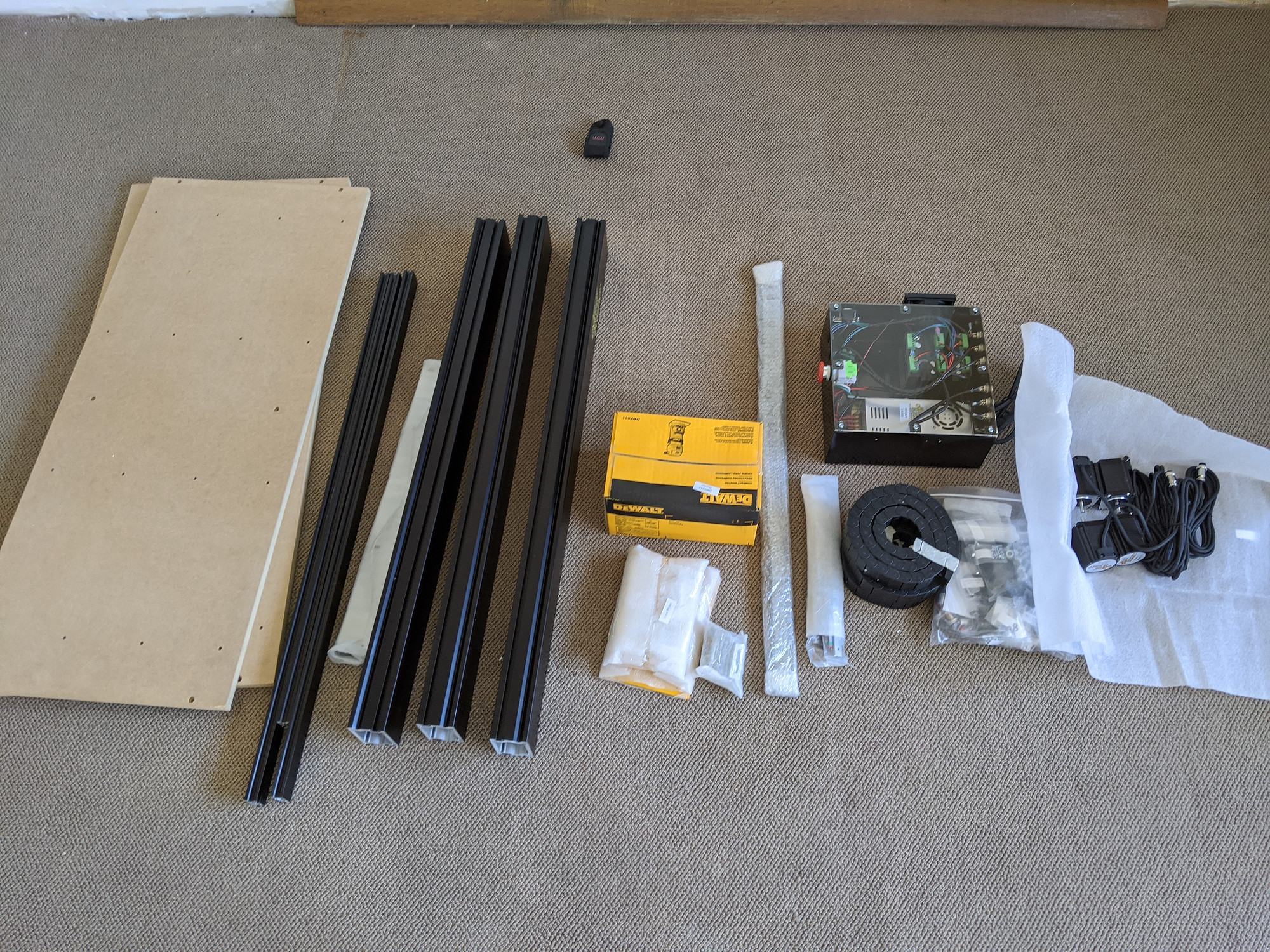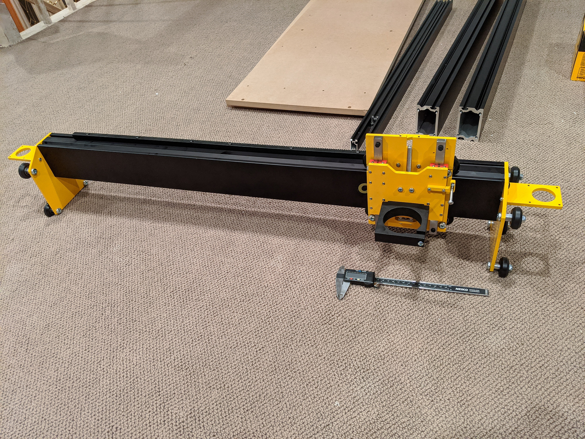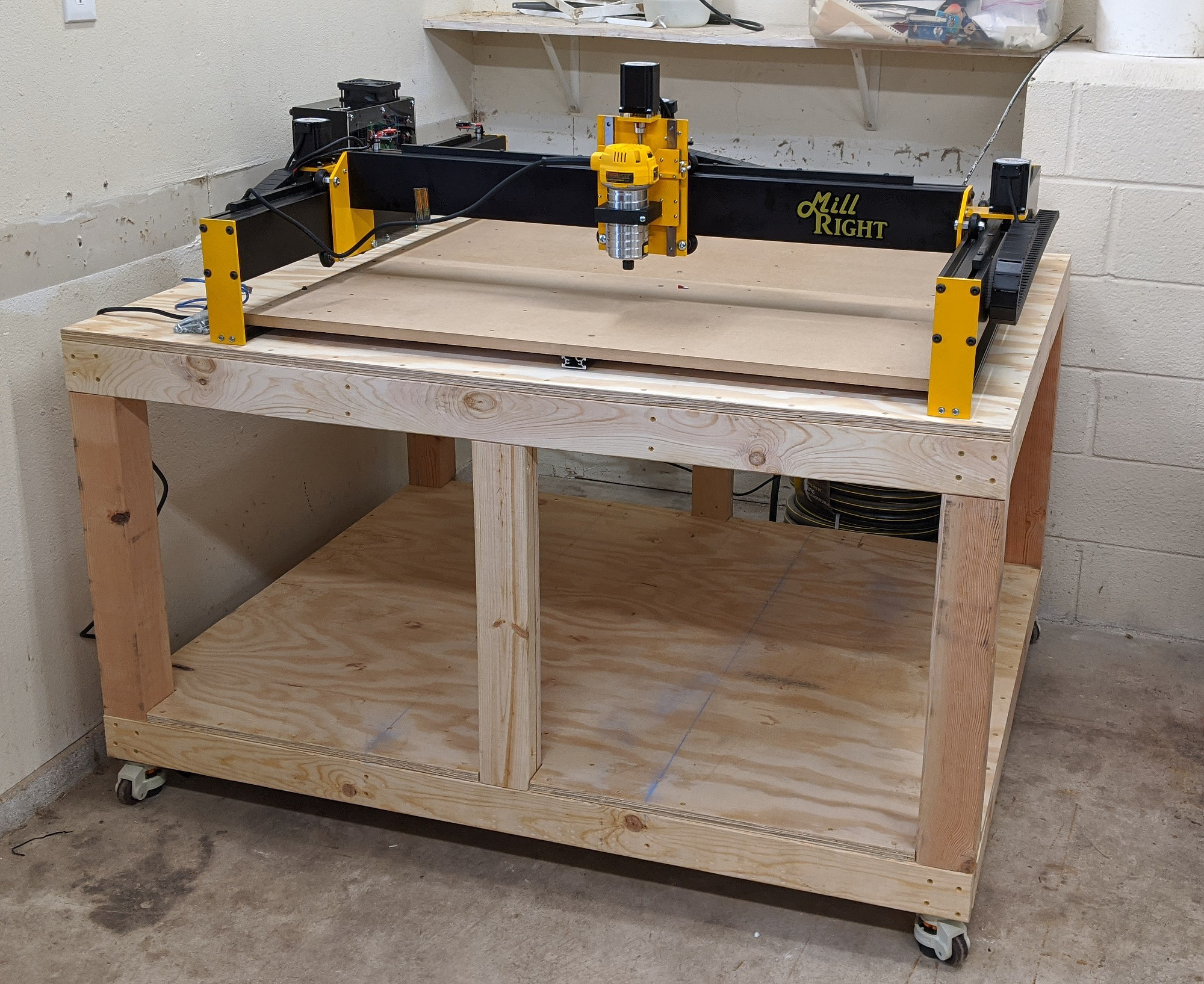

The stock spoilerboard included with the MDF version of the Mega V uses t-nuts for workholding, but they’re pretty sparse to begin with (example here)
I knew that I wanted to add a supplemental wasteboard that could be surfaced and replaced easily, and started looking for other options.
From what I can tell, the most common options here are:
- No special workholding: Screw, glue, nail, or even plastic pin nail in your pieces and/or workholding devices directly into the spoilboard. This means that setting up the wasteboard is easy and inexpensive, but it does suffer some extra wear.
- T-nut and holes: Pretty easy, plenty strong, not too expensive.
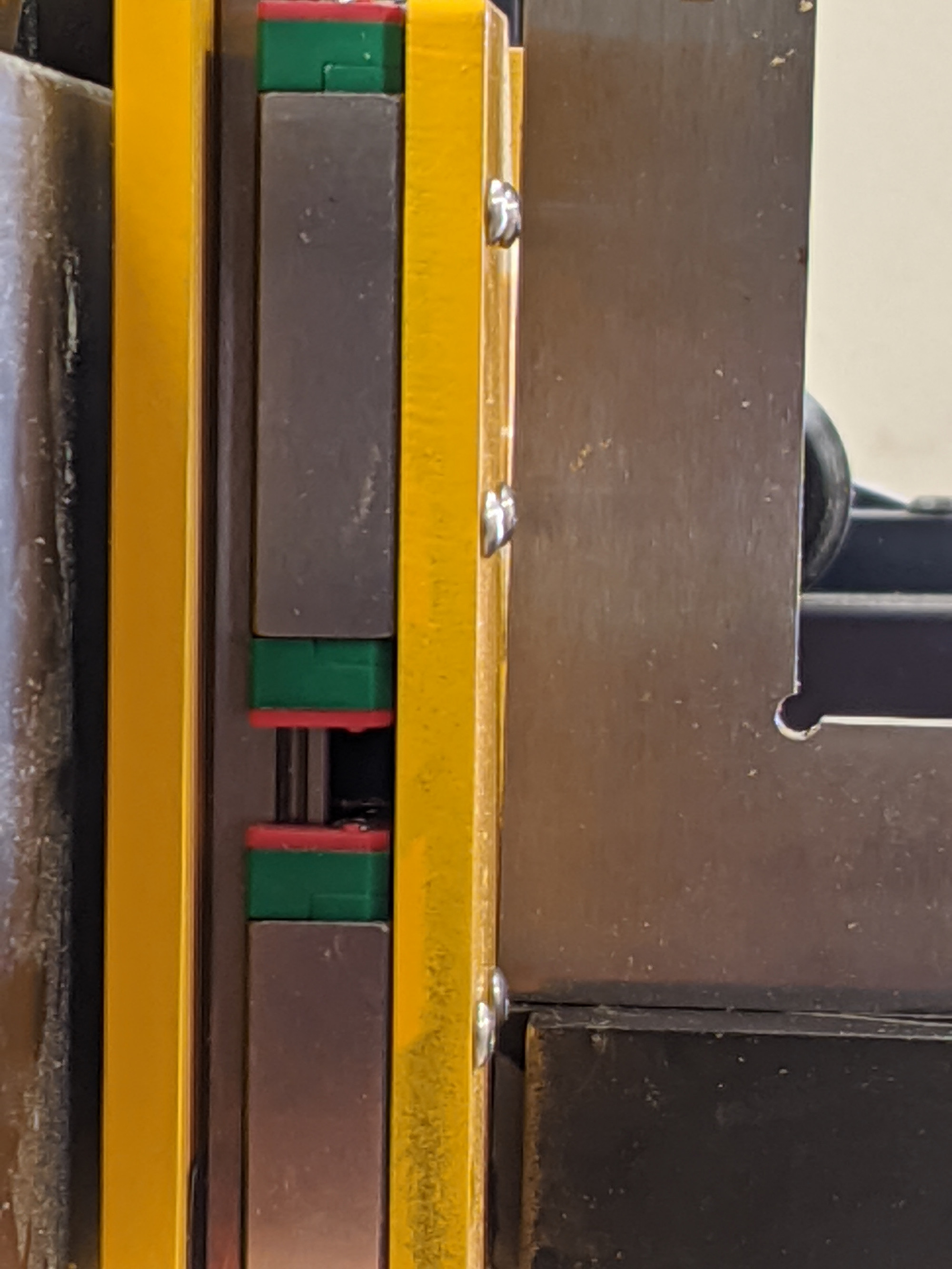
- Aluminum t-track slots: The track is fairly easy to set up, but does require some extra t-track hardware, as well as the tracks themselves. The board between the tracks can use strips, allowing better use of large material sheets.
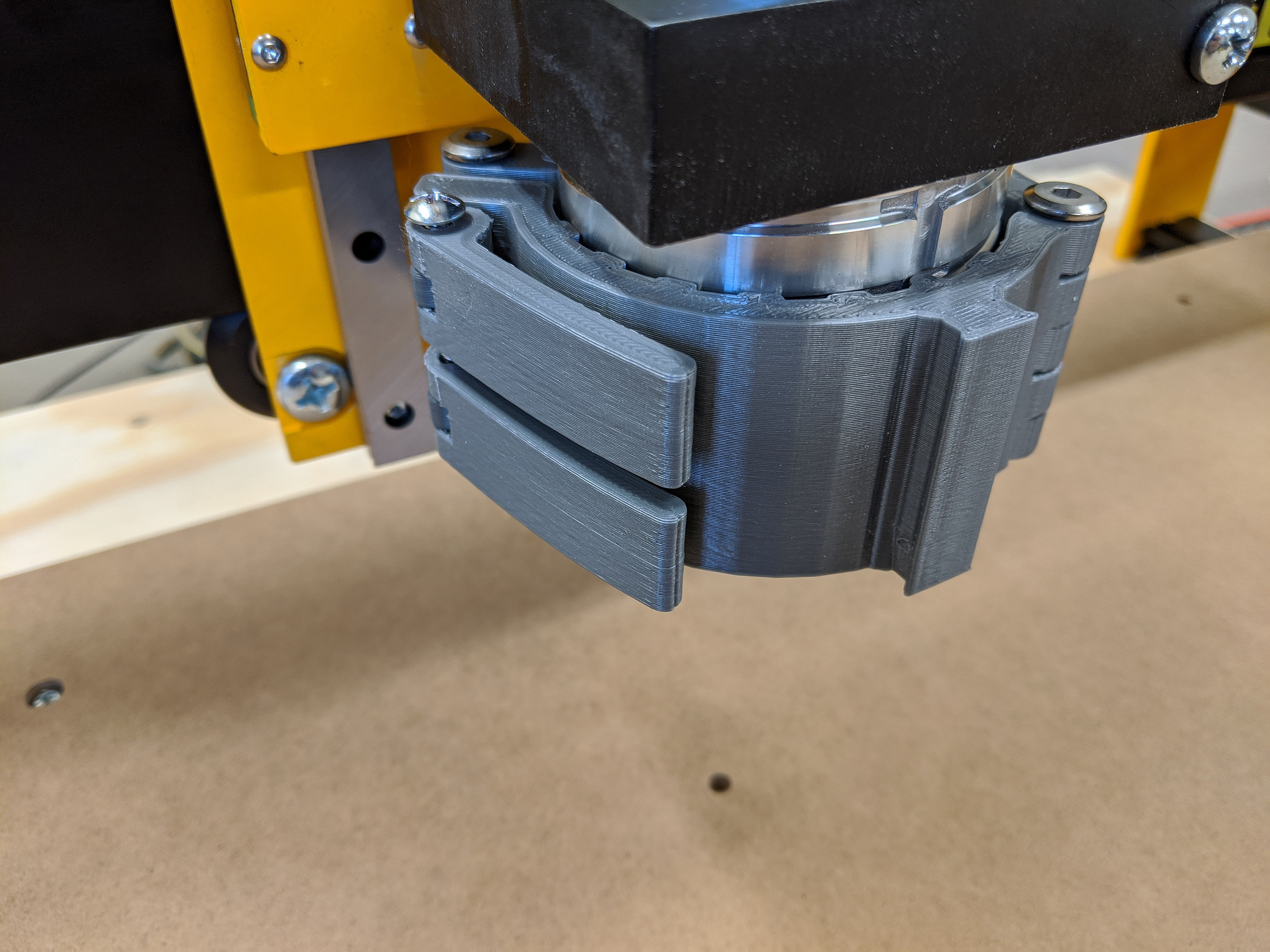
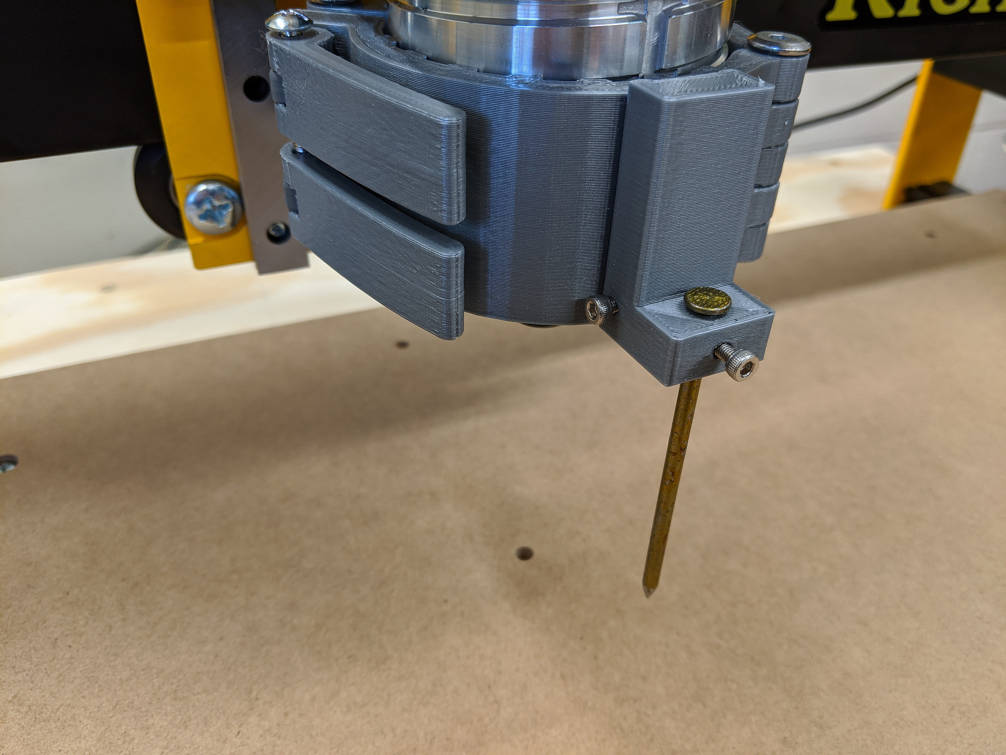
I was planning to use aluminum t-tracks, which were only marginally more expensive than the t-nuts, but stumbled on a couple of examples of using dovetail grooves instead:
- https://wiki.shapeoko.com/index.php/V_slot_bed
- https://www.thingiverse.com/thing:3728184
- https://www.reddit.com/r/CNC/comments/fhftb9/my_spoil_board_work_holding_jigs/
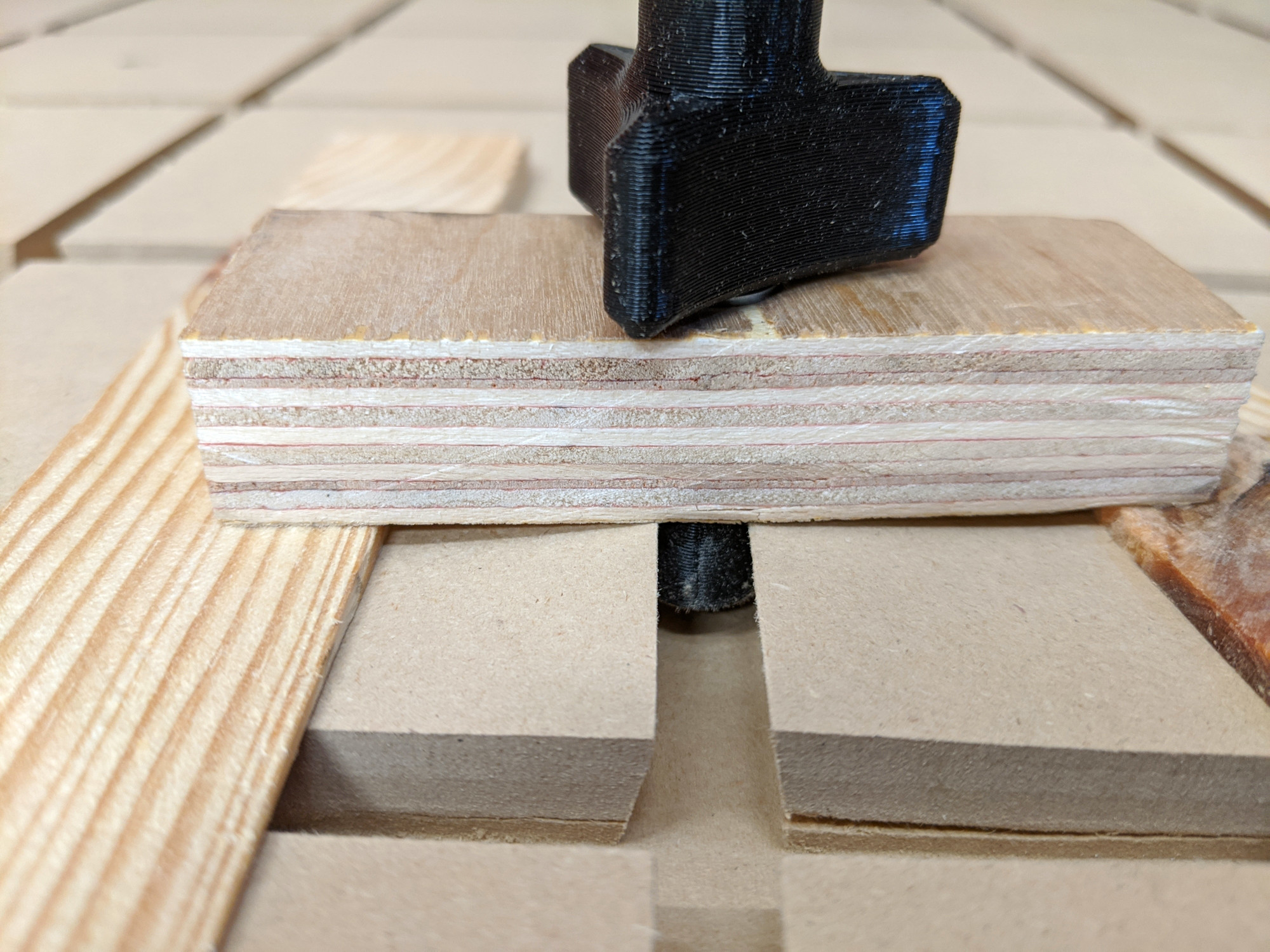
These slots have a couple of cool features. They’re cheaper (depending on what you use for fixture hardware) and allow for very dense workholding, in any direction, at any spacing.
They do have some (significant) disadvantages though, some I recognized during planning, and some only later.
Disadvantages
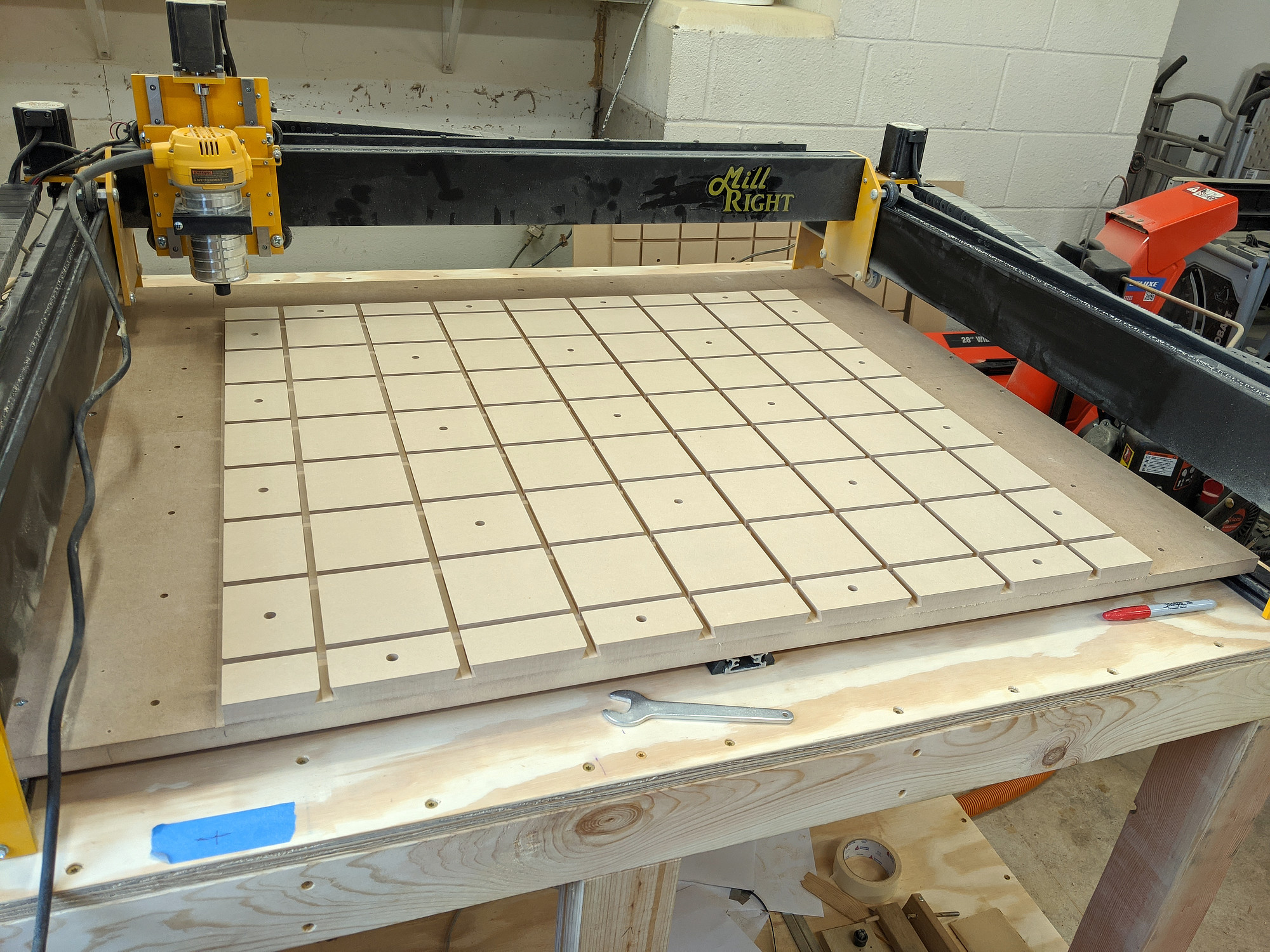
Tearout
When using these grooves with MDF wasteboard, you must, 100% of the time, use clamps which press directly against the wasteboard surface at the clamping point, or the MDF can absolutely shear out. I was easily able to tear out an entire 4” square section by hand with the clamping pressure spread away from the slot. This eliminates many of the most common types of clamps.
Available space
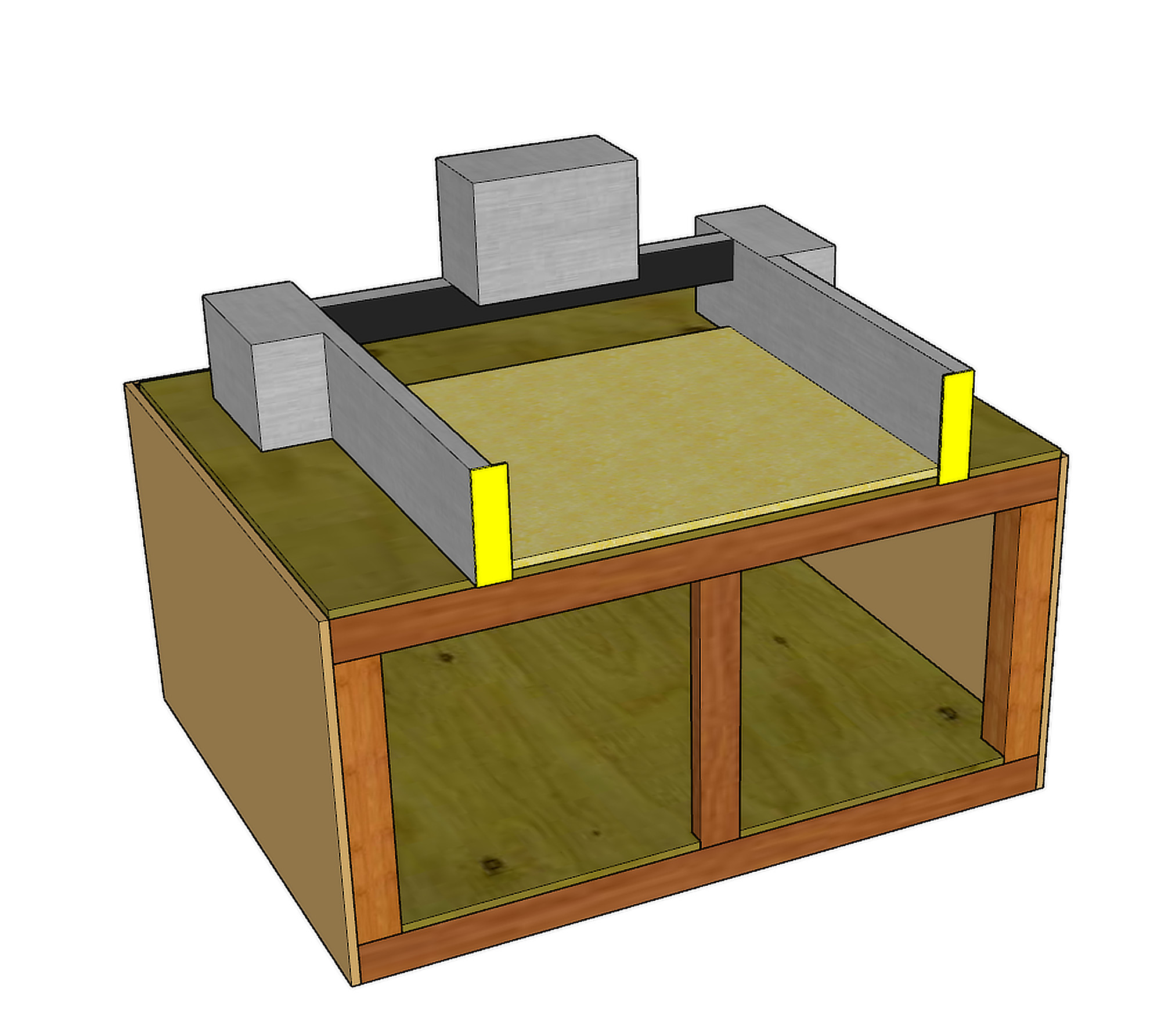
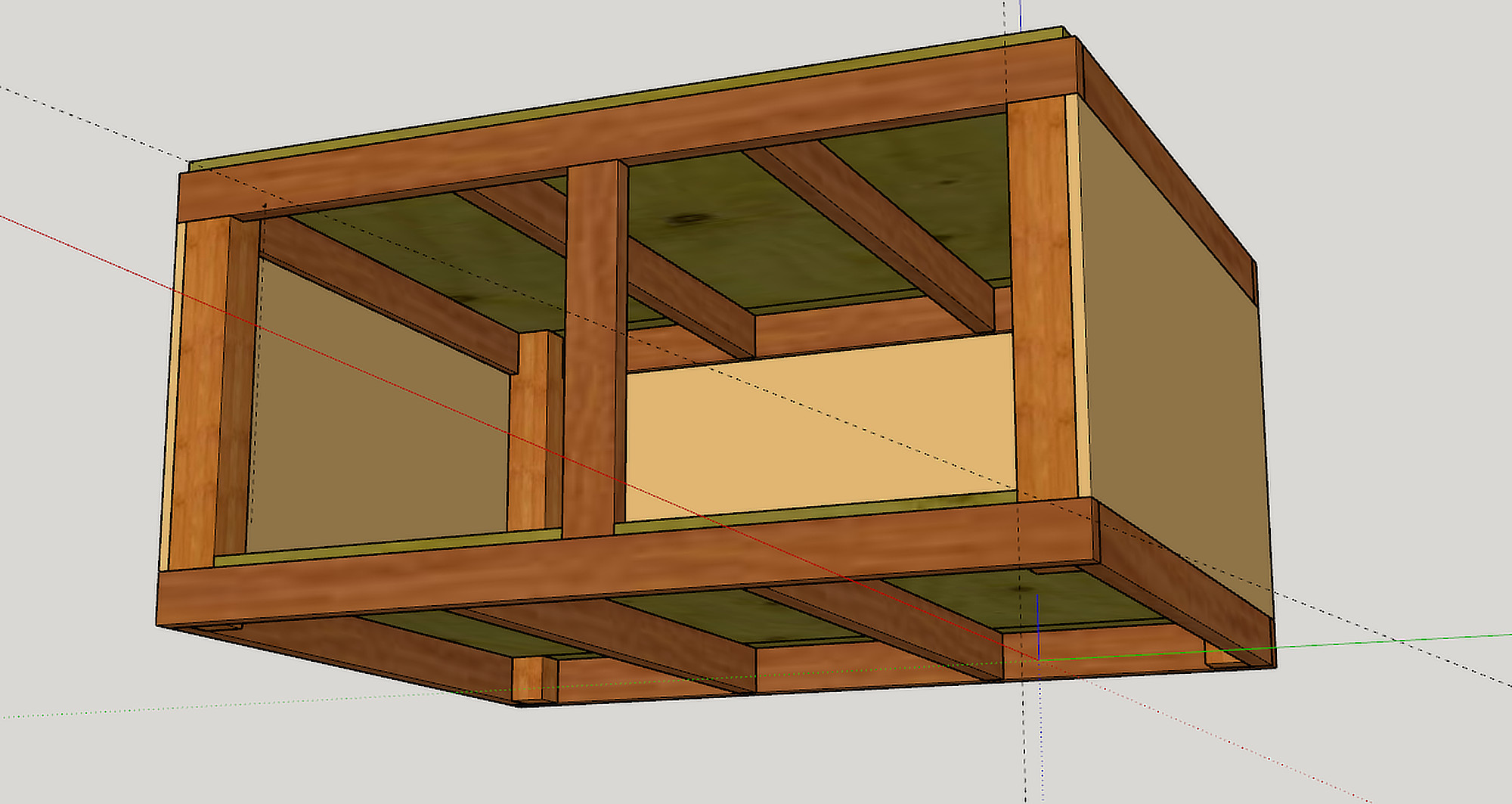
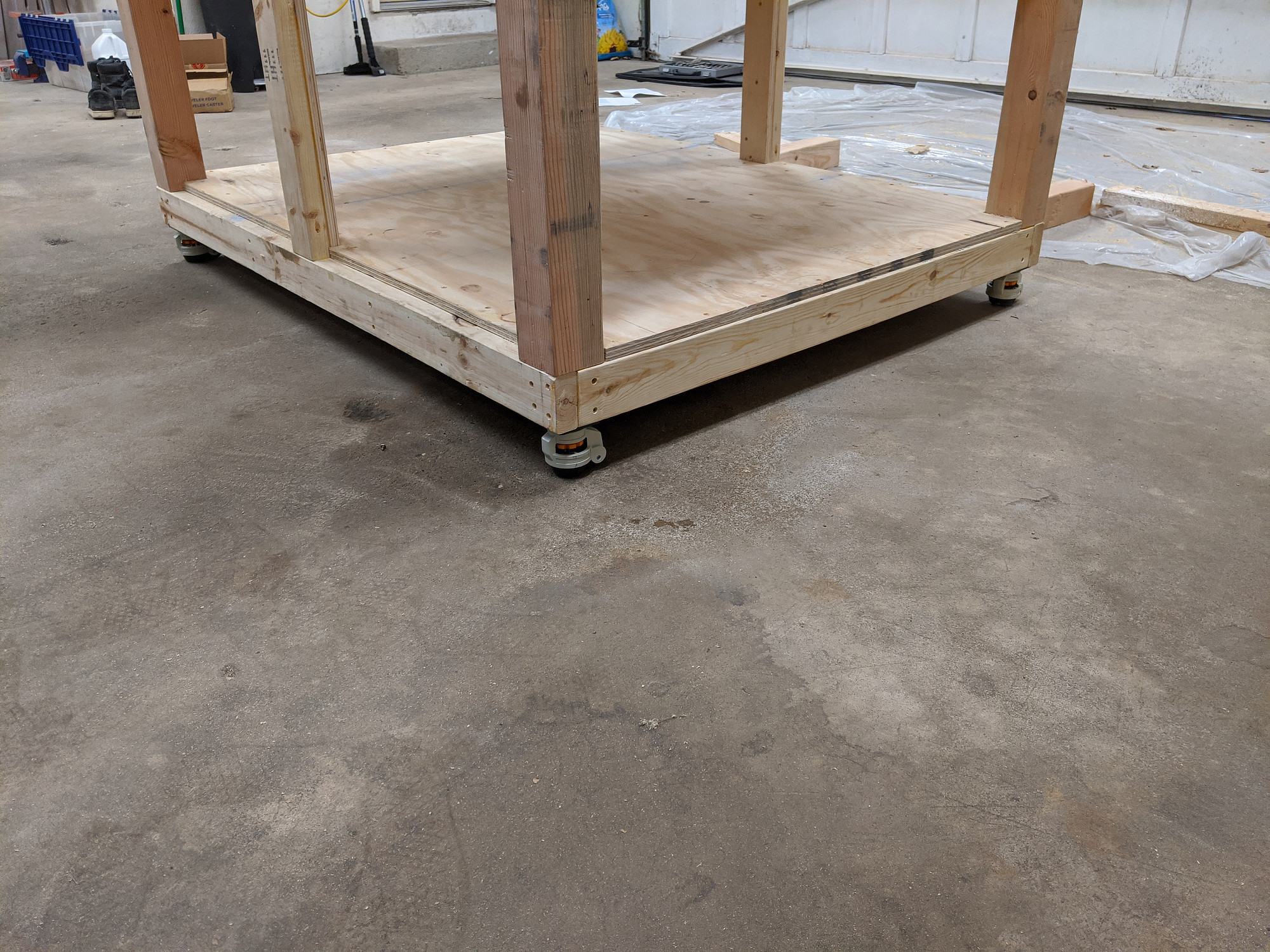
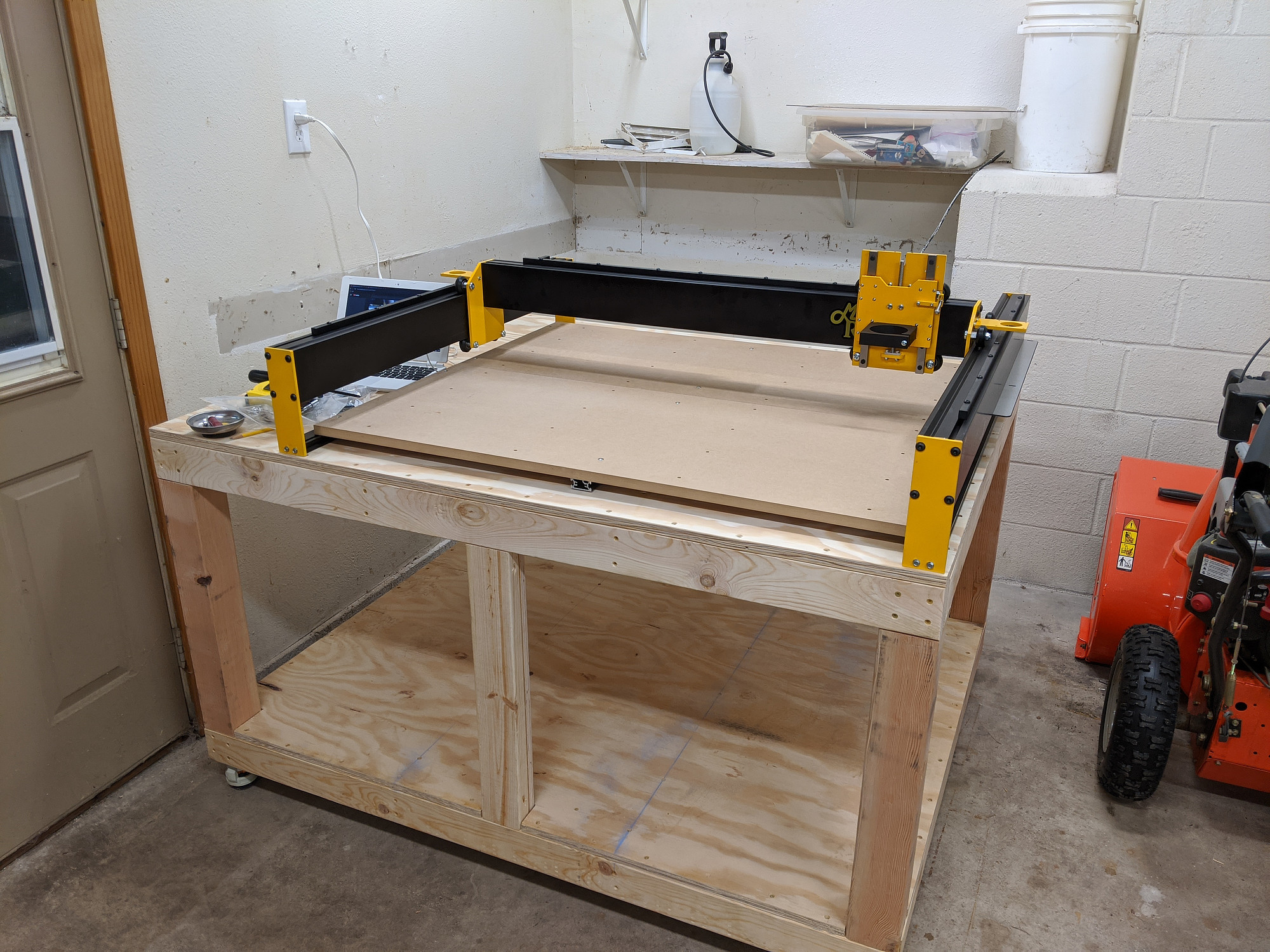
I’ve reduced my available space a few ways with this board. First, by putting another 3/4” board on top of the existing wasteboard, I’ve lost a pretty good chuck of my machinable Z height. I’m already planning a new stock and secondary wasteboard to reduce the height.
In order to route the slots with the CNC itself, using a 1/2” dovetail bit, I needed a little clearance on all sides for the bit to enter and exit the edge of the board, so this reduced my X and Y range as well.
Lastly, I wanted the router to overhang the end of my spoilboard a bit so that I can (hopefully) cut dovetails in upright stock, so I slid both spoilboards back a couple of inches, which reduces the Y range a little more.
Resurfacing
I have a bit of extra room, but I’m limited it how many times, and how deeply I can resurface my wasteboard before the inserts no longer fit correctly. I can reprint them easily when that happens though.
Ease of use
While these can be easy to set up, they rely on a pretty good fit inside the slot. This means, though, that they’re harder to get in and out when the slots fill up with chips.
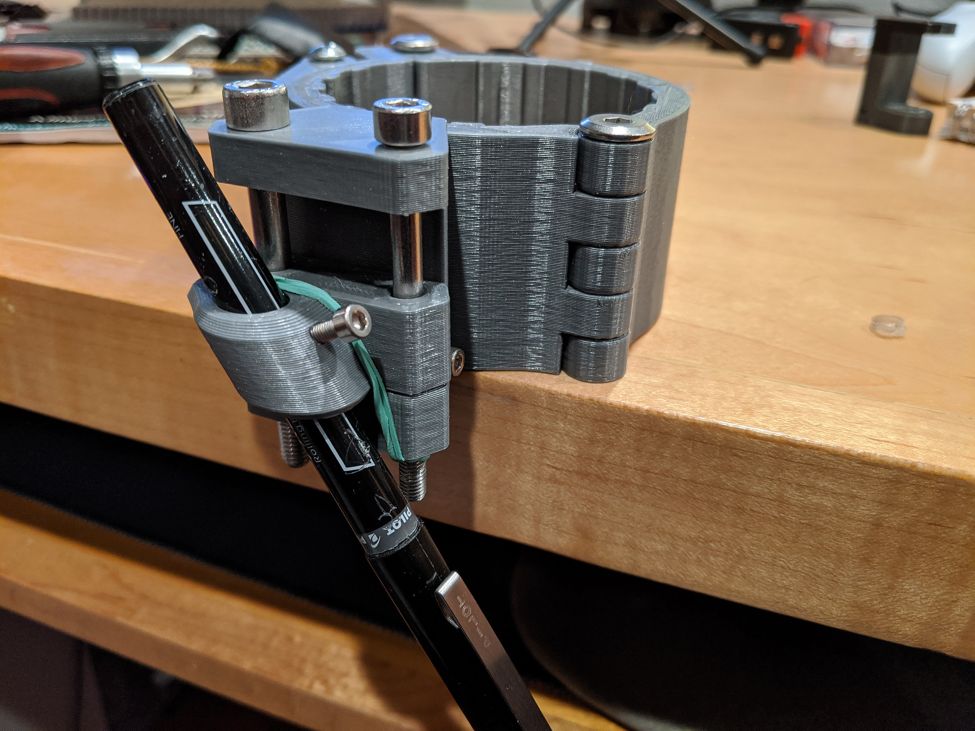
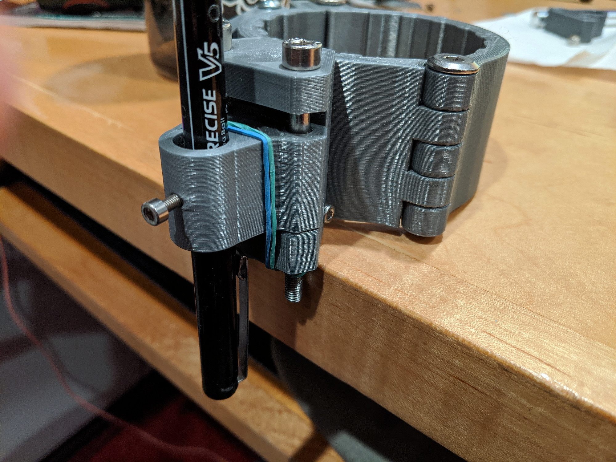
They get stuck
More on this later, still trying to figure it out, but I often have to unjam these from the slots after use.
First attempt (spoiler)
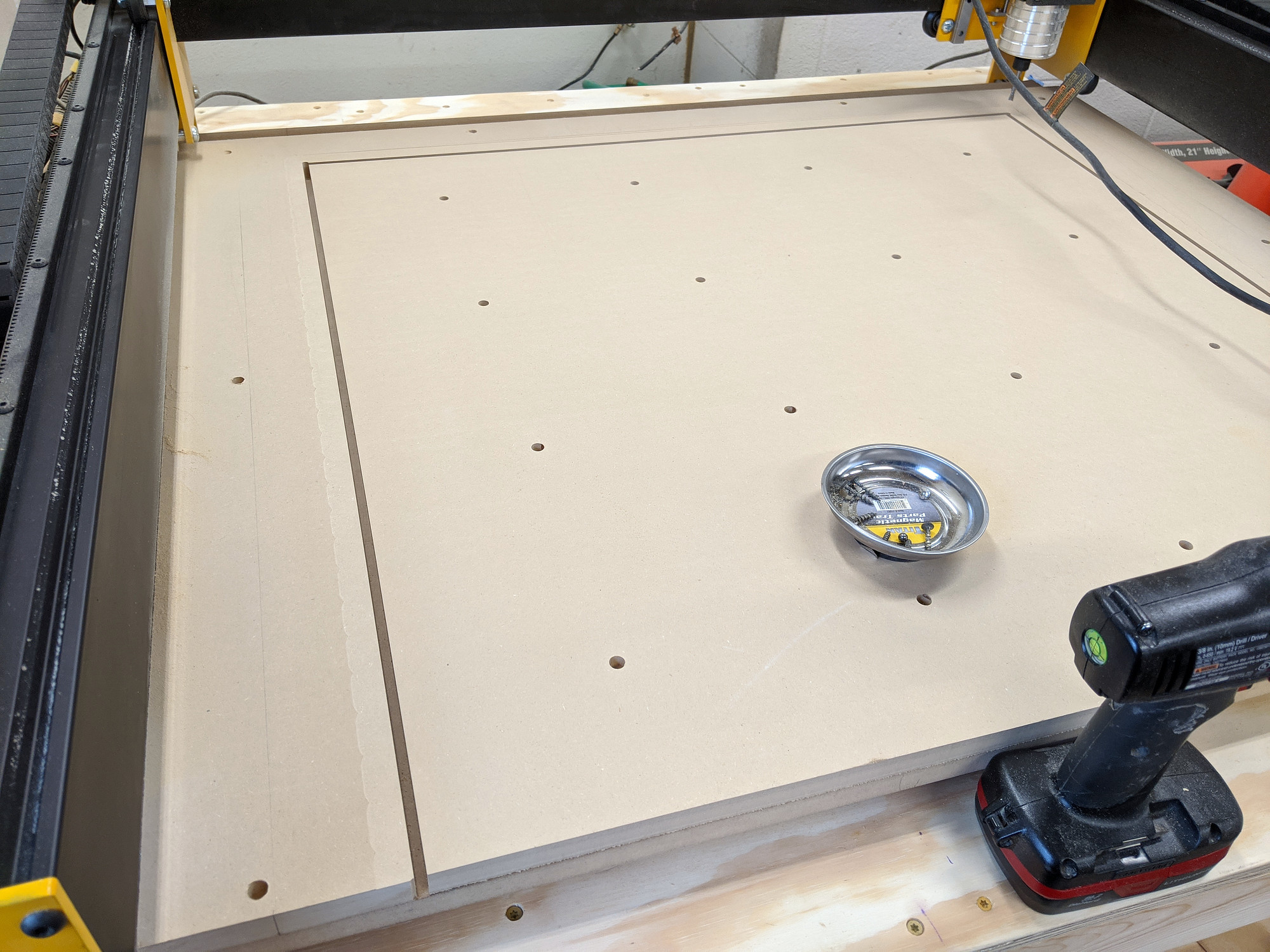
First, I cut a section of MDF, a bit oversized, and temporarily fastened it to my wasteboard using drywall screws around the outside edge. I really want to find a better fastener for this but haven’t yet.
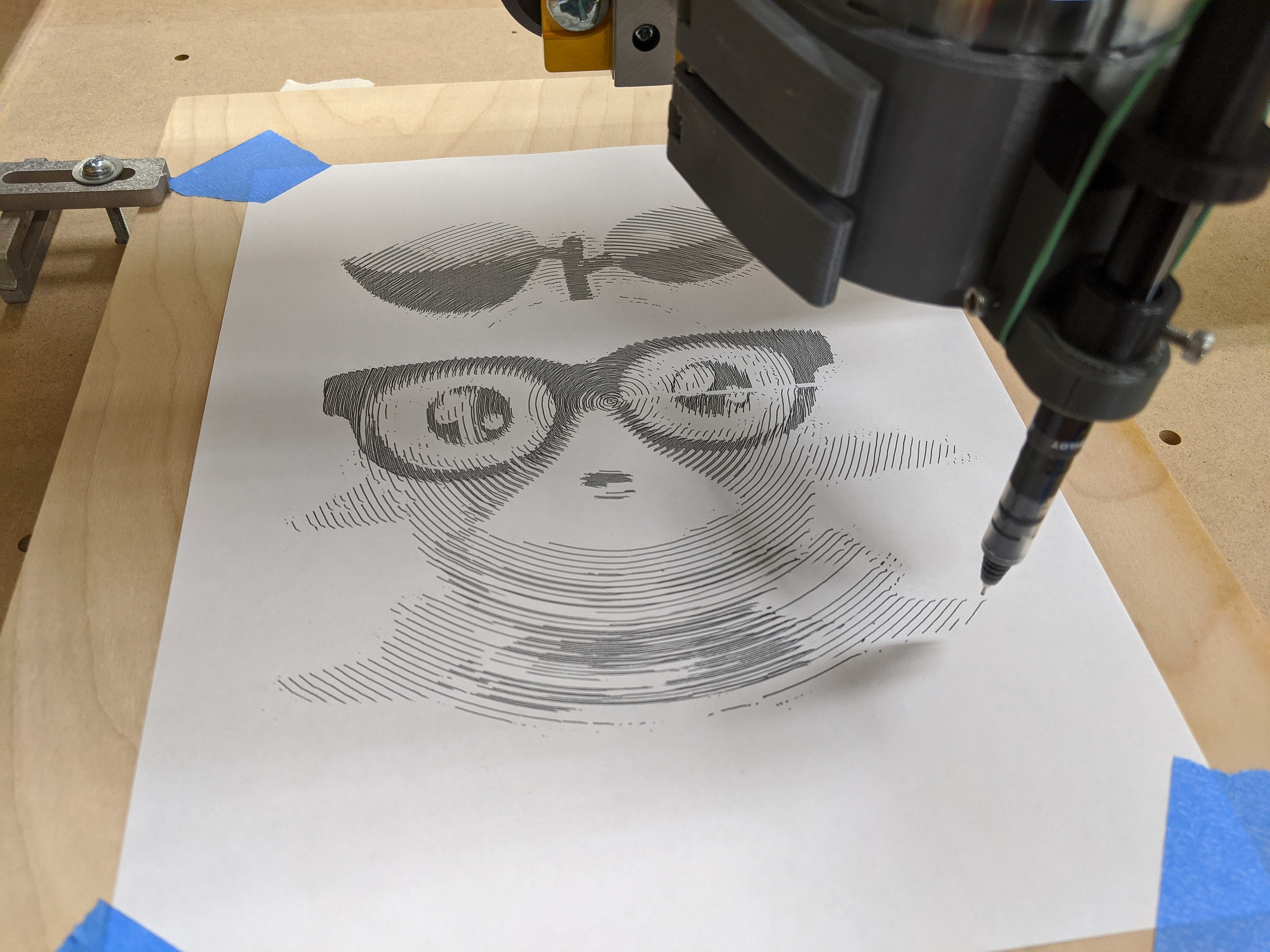
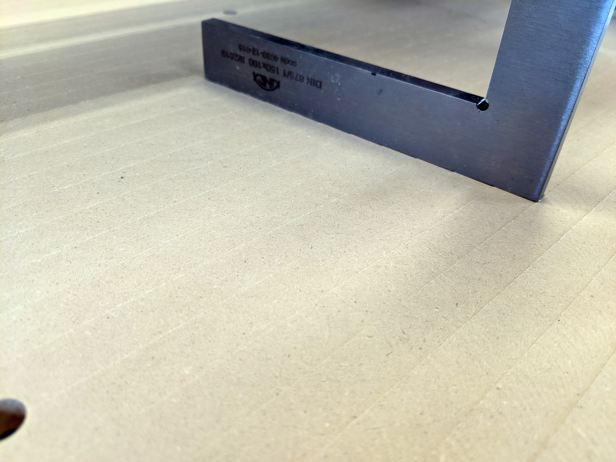
Then, I set up some operations in Fusion 360. First, I surfaced the area of the wasteboard that the CNC could reach, enough to take care of any real high spots and/or warping. This also showed just how out of tram my router was, with a huge nod forward. After some investigating, most of this nod was coming from badly off-square router mount. Once that was shimmed back to square, there was enough play at the router to get it close to trammed using a simple tramming tool.
Then, using a 90 degree chamfer bit, I made some spot markings for the holes that would fasten the new spoilboard to the stock one.
These I then hand drilled, deeply countersunk, dropped some CA glue into for a little more longevity, and finally fastened down.
I then ran a 2D contour toolpath to cut the excess MDF free and removed the temporary screws.
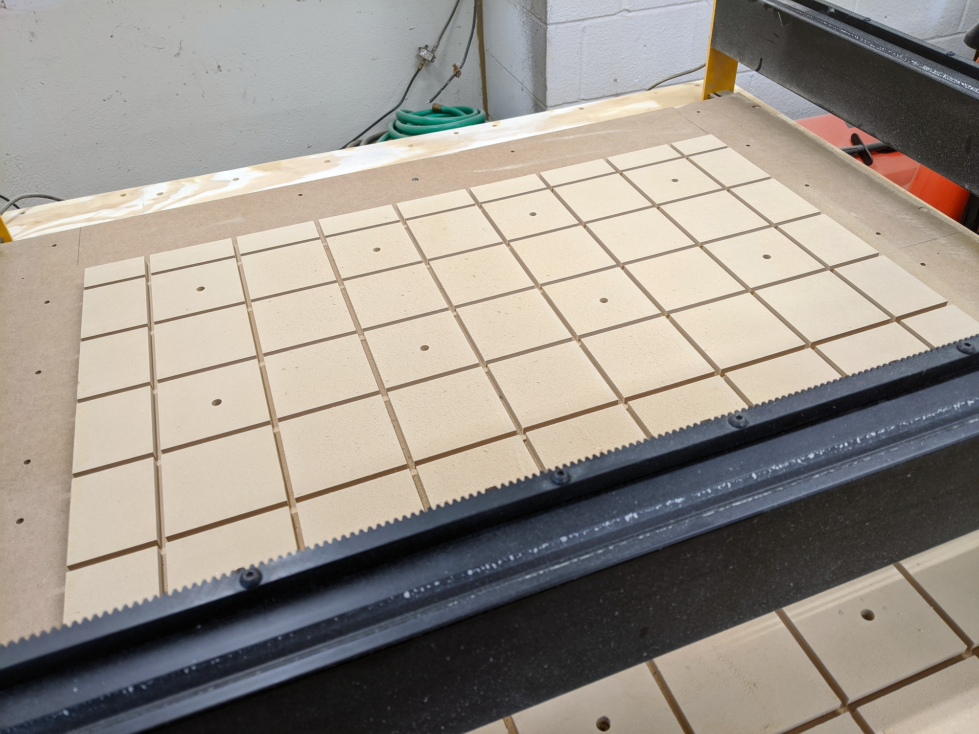
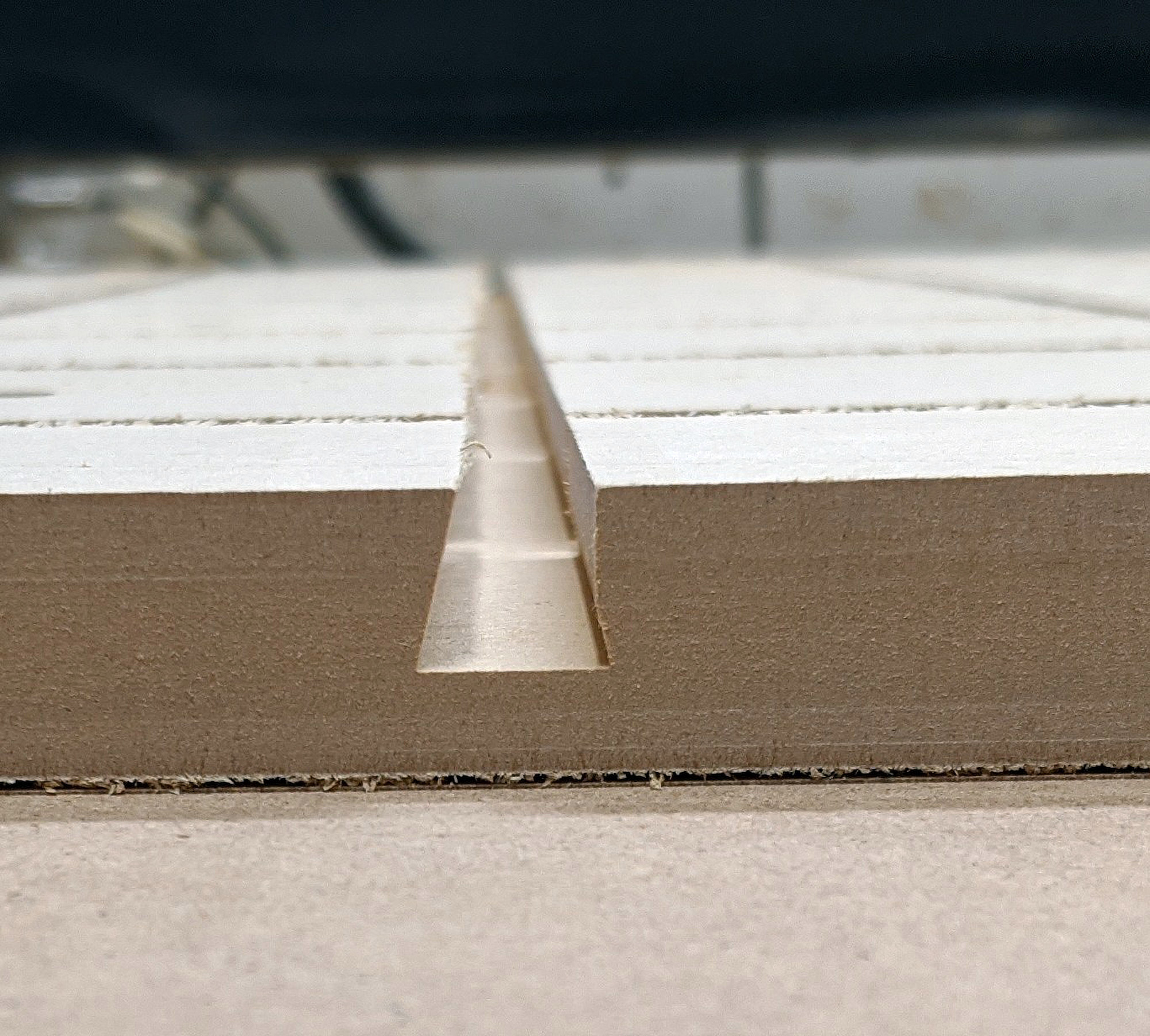
After the wasteboard was fastened and cut free, I made some relief cuts for the dovetails just under the final depth with a 1/4” downcut endmill, and then ran the dovetails in the same slots.
Here I had some trouble, and had to start over.
First, with the relief cuts and dovetails, the MDF wanted very badly to curl up. Some of my screws were around 5” from the edge of the board, and that was enough for it to want to lift.
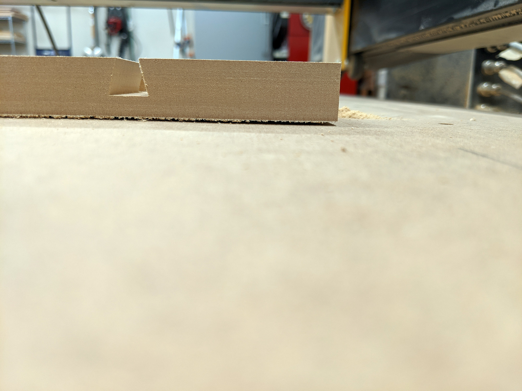
Secondly, somewhere along the way, I lost some steps in the Y direction, and a couple of my dovetail slots were both the wrong shape and size (due to them not being centered on the relief cuts).
Second attempt
I went back to fusion and moved the screw holes around. I increased the density of the screws, and made sure they were fastened close to the edge as well.
Since the process of manually drilling these was such a pain, I also set up a toolpath to bore these down to final depth instead of just marking them, leaving me to only need to countersink, drill, CA glue, and screw each of them, which was still a pain, but one step fewer.
Afterward, I ran through the same steps as before. I’m not sure when the missed steps happened. Maybe I crashed something. At any rate, I didn’t end up with any missed steps for the second attempt.
I also took the time to set up an extra toolpath to cut beveled openings in all of the slots. It was really satisfying to see these run successfully.