

After finishing the dovetail grooves, I started on workholding and clamps by designing and 3d printing some dovetail inserts and knobs.
Dovetail fittings and knobs
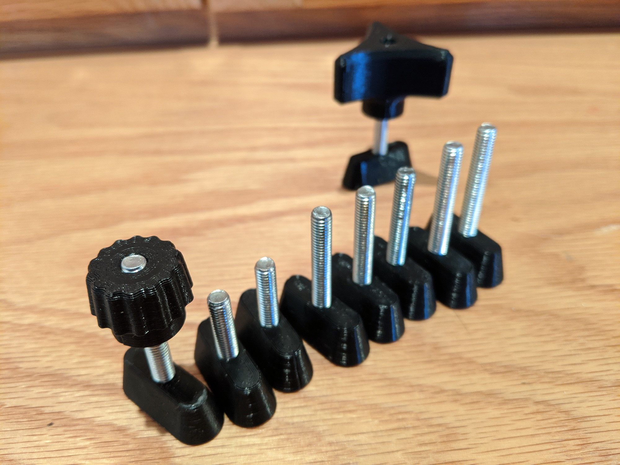
I tried a few different bolts, but settled on 40 and 50mm M5 hex bolts. Any longer, and I have trouble clearing them with my router (and extra spoilboard).
For clamping taller blocks, I can counterbore them to recess the clamping knobs into the material a bit, and this helps keep the clearance height down a bit.
The inserts and knobs went through a few iterations.
The inserts got a little smaller in width, so that they can slide in the dovetail grooves more easily, and a deliberately undersized nut diameter so that the bolt heads fit tightly in them, instead of being easily pressed in.
Most recently, I also made them a little bit shorter, so that I can surface the spoilboard a few times, but also to make sure that when clamping they don’t press directly against whatever it is I’m clamping, causing them to slide even when clamped tightly.
These are not perfect though. With tight clamping, these get stuck in the MDF. I’m not sure if the MDF is getting deformed and snapping back when pressure is removed, or if the layer lines in the 3d print are kind of biting into the MDF surface, or if they’re getting jammed by rotation.
After clamping tightly, I usually have to uncscrew the knobs, pull off the blocks or cam clamps, and then poke the inserts back into the slots with a screwdriver to free them up. I’m not sure how to solve this yet. I’ve tried a few variations so far.
- Sanding and polishing the inserts so that layer lines are soft and smooth
- Increasing the taper of the inserts, so that they’re tighter toward the bottom of the slots
- Rounding the top of the inserts so that the edges are less likely to gouge in
- Adding reliefs in the sides at 10 and 4 o’clock, so that they’re less likely to get jammed by rotation.
I haven’t notice any difference with these though.
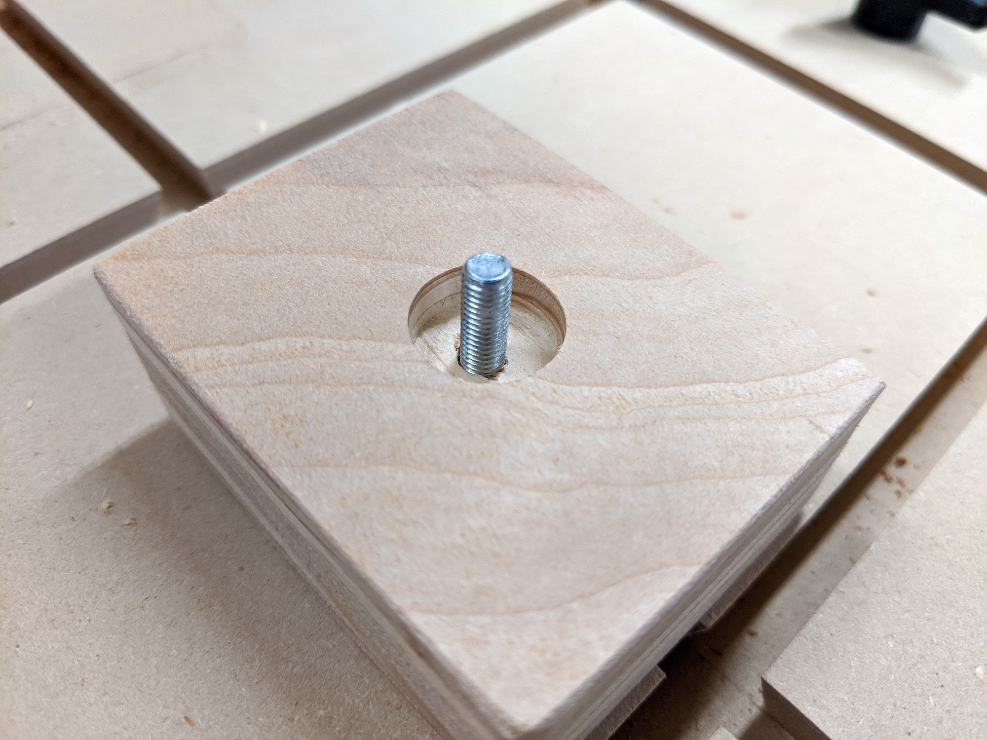
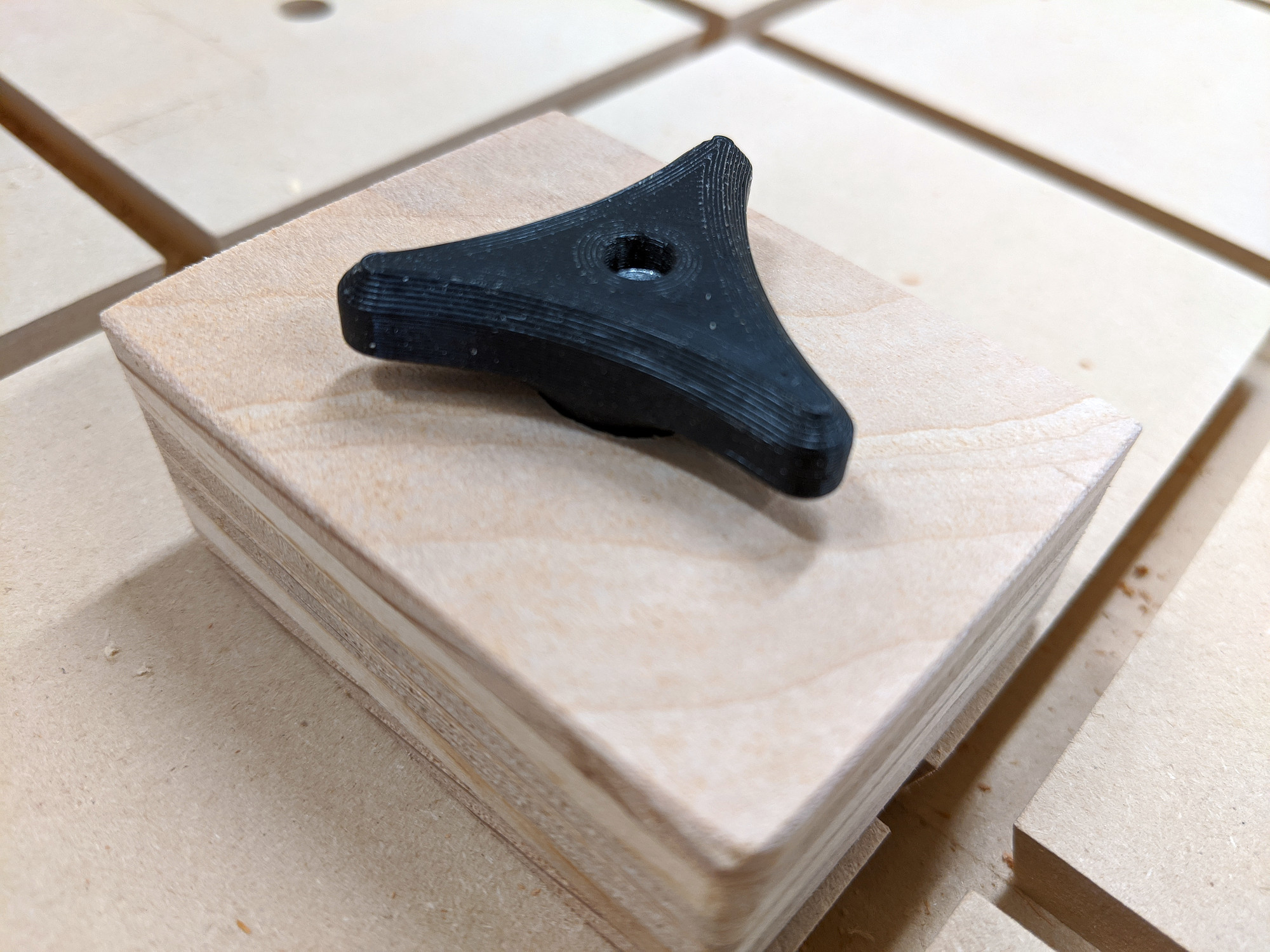
Stop blocks
I started by just drilling 5mm holes in random bits of scrap wood. This works fine with enough lateral and downward pressure but quickly realized they work much better if they’re a little taller than the material being clamped, and also have a slight 15° bevel on them to help keep the material down. Seems obvious in retrospect.
These I just cut on a table saw, and then drilled a hole roughly in the center.
Cam clamps
These are simple spiral-shaped cam clamps that apply sideways pressure, but won’t hold anything down.
I cut these from 3/4” plywood, and they work great.
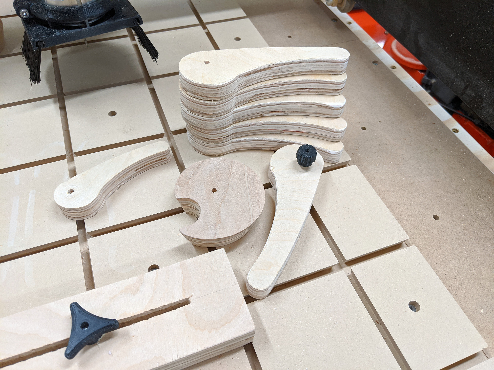
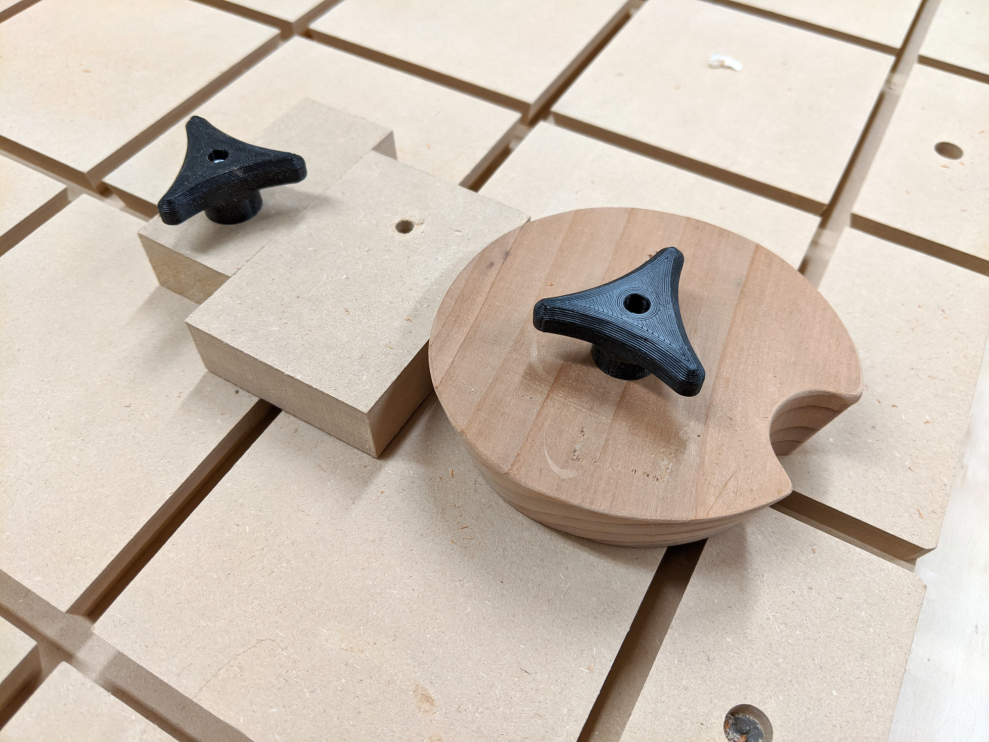
Round cam
The above picture also has my first pass at a round cam clamp, cut from scrap redwood. This one is one inch thick and has the same 15° bevel on it to help hold work down. Before cutting it, I drilled two holes through it surface and held it in place with flange nuts rather than clamping.
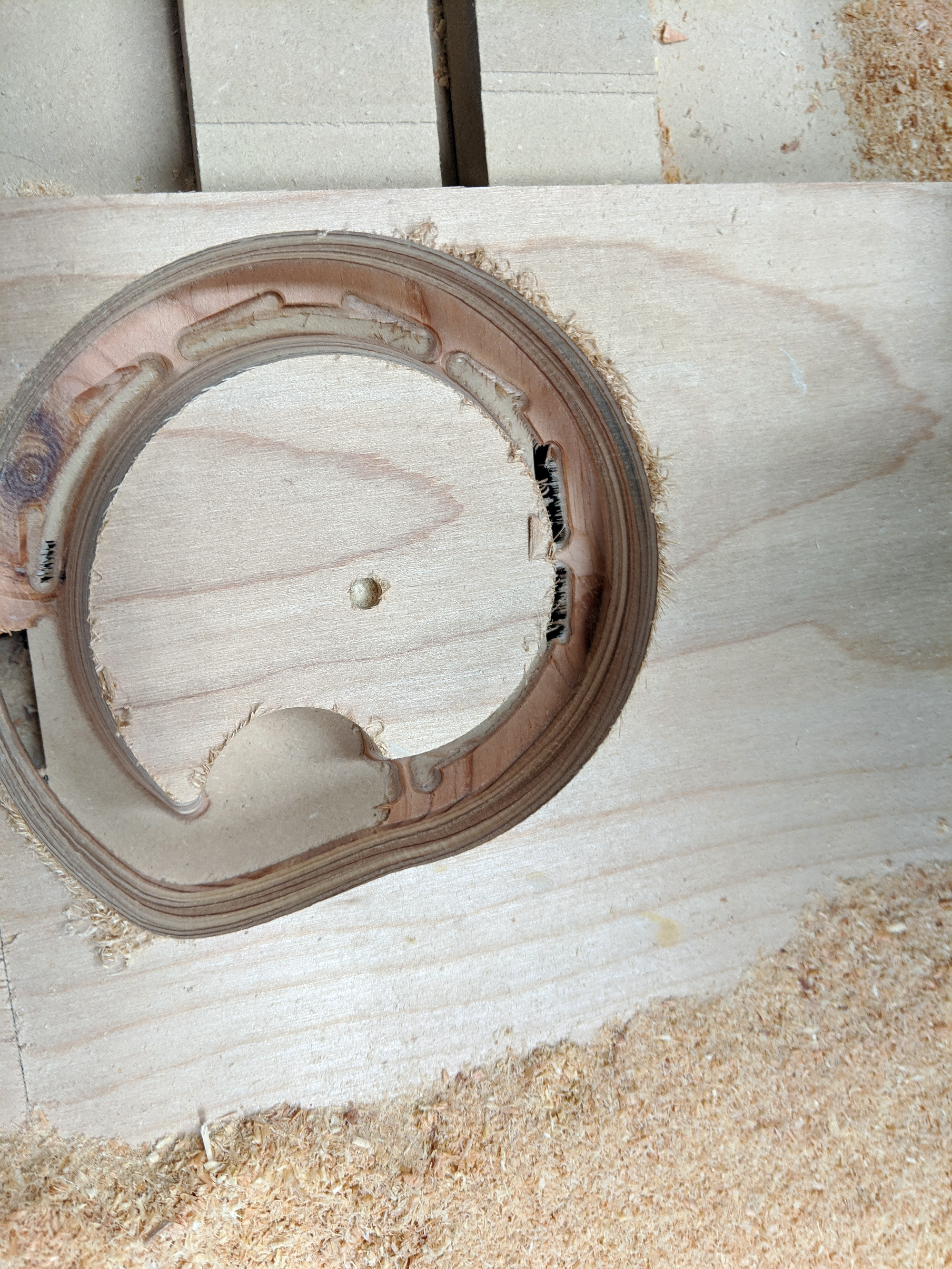
This was roughed with a 1/4” square endmill, and then finished with fine passes with a 1/4” ball endmill. This could have been made much easier and faster without the CNC, using a bandsaw and an a tall bevel bit, but I don’t have either.
Here’s what it looks like in use.
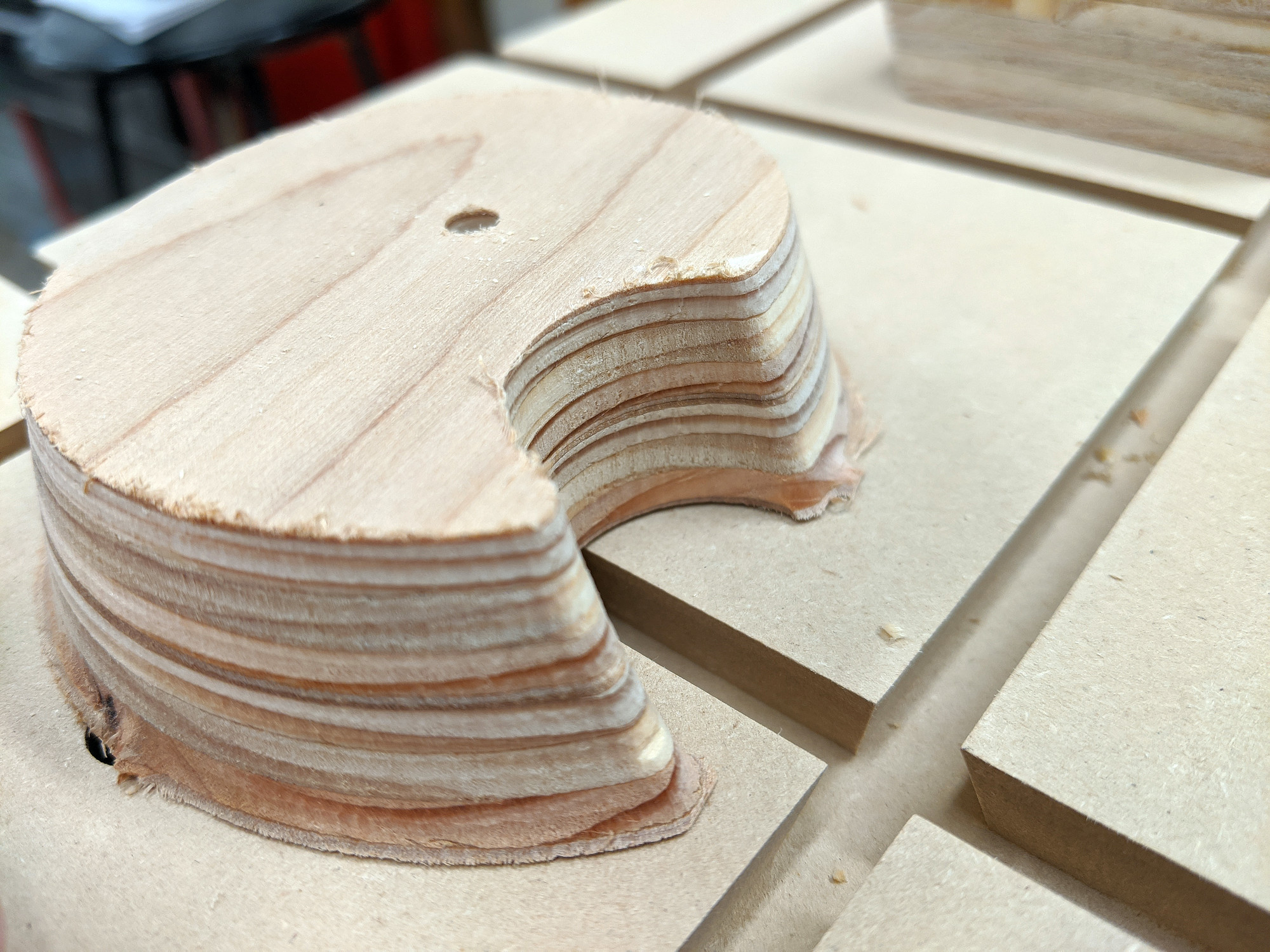
I refined the shape a bit, so that it has a smooth spiral from beginning to end, instead of having some lost space around the perimeter that can’t be used for clamping, and cut a new one from 1” plywood (really two 1/2” sheets sandwiched together).
Instead of bolting through it, I modeled tabs for it manually in Fusion.
Low profile clamp
One issue I’m having with these styles of clamp is that they have to be taller than whatever I’m working on to have any holding power (at least downwards).
I’m experimenting with low profile sliding clamps, and just finished designing and assembling this one (a rebuild of one I found on thingiverse to fit my hardware).
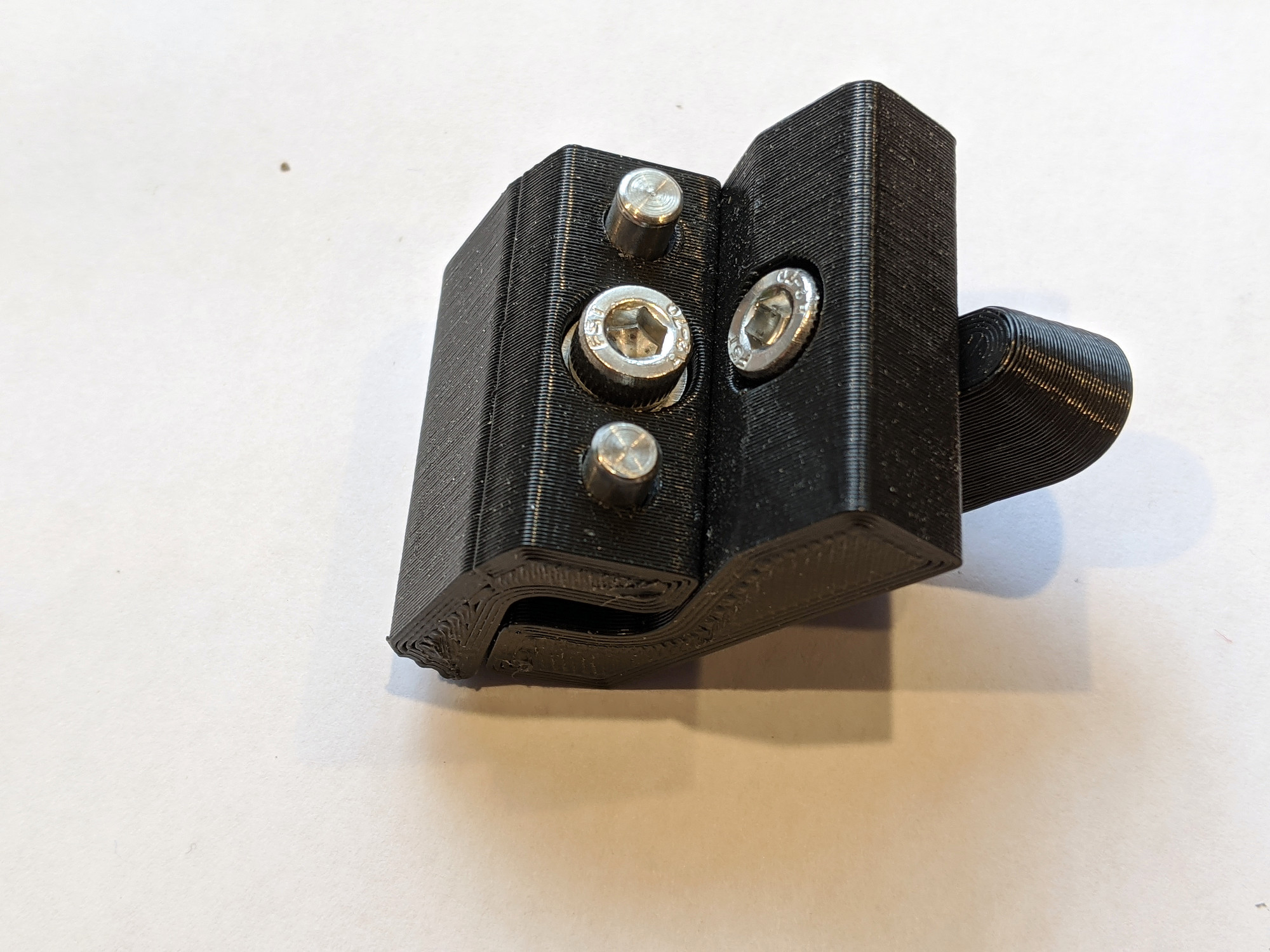
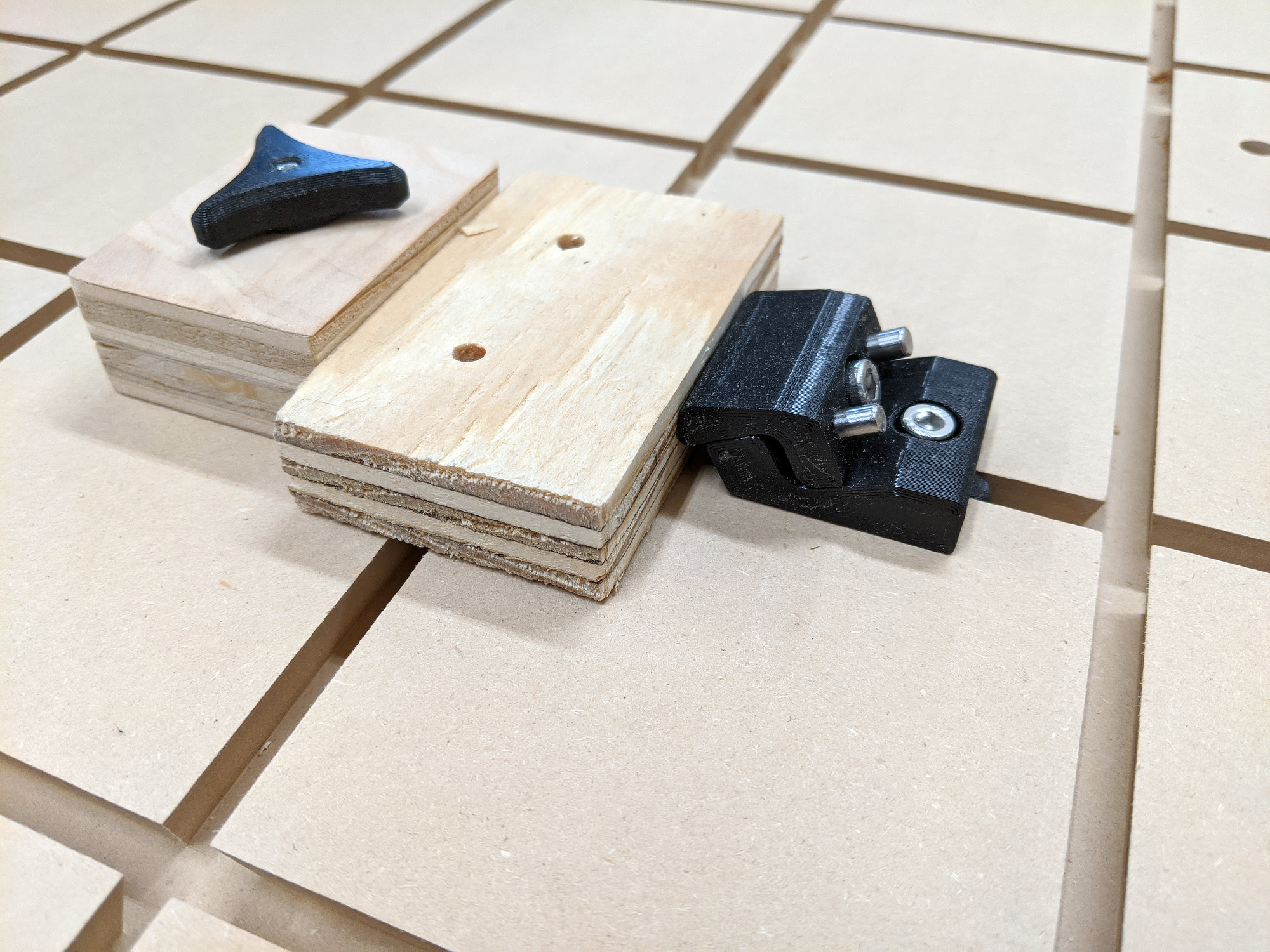
This uses a M5 18mm socket screw (I’m really using a 16mm but it’s a little short) for the sliding part, a M5 16mm screw to hold it to the dovetail insert, and a couple of 5x25mm steel dowel pins.
It holds fairly well, but I haven’t tested it thoroughly yet. It may not be better than any other side clamp, especially since the “teeth” are quite dull.