I built this last year, but completely forgot to post about it. As such, it’s a bit detail-light.

Okay2 synth with closed case

Reasoning

I was looking for a small keyboard that I could use to sound out musical phrases or chords, while learning other instruments.

Notably, I wanted:

  • 1.5 to 2 octaves of notes
  • Standard piano layout
  • Small enough to fit in my desk drawer, around 10.5” wide by 9” deep
  • Two or more note polyphony
  • Buttons for keys (rather than a stylophone)
  • Close enough to accurate tuning

There are some midi controllers that meet these requirements, but I was looking for something standalone, with it’s own speaker.

I couldn’t find any commercial keyboards that did those things, but I did eventually stumble on the (delightful) Oskitone site.

They have a number of fun noise makers, including the poly555, an analog keyboard based on twenty 555 timers, and the scout, a hackable microcontroller-based synth.

A number of these also have 3d models available for 3d printing:

https://www.thingiverse.com/oskitone/designs

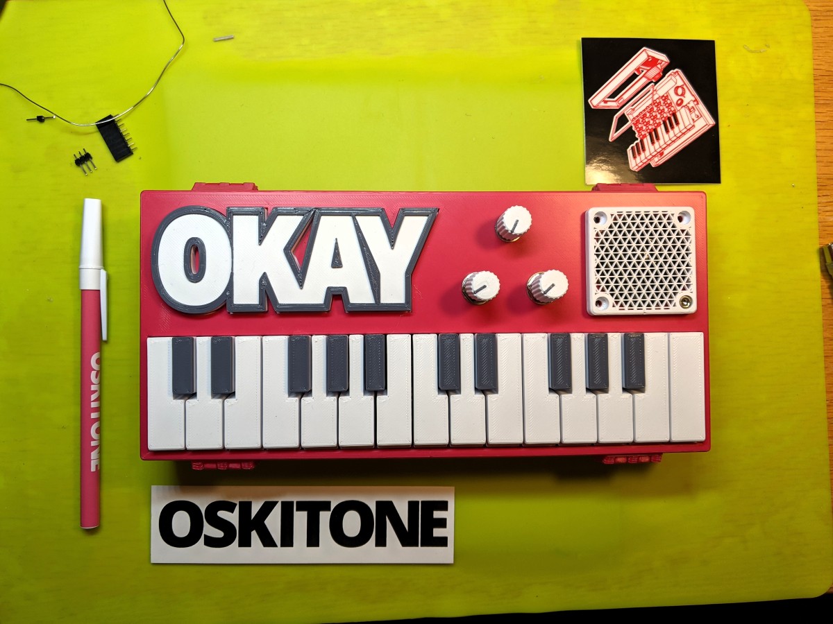
I settled on the Okay2 synth, as it had the dimensions I was looking for (around 9.25” wide by 4.25” deep), two octaves of keys, and it looks cute.

Build

Internal wiring
Internal wiring

Instead of using Oskitone’s components, I chose to build out the internals myself. Initially, my goal for this was just to allow more notes to be played simultaneously, but the features got away from me a little as the project went on.

It currently supports the following:

  • full polyphony
  • eight sampled instruments, pulled from Microsoft’s sound fonts
  • selectable octave
  • volume control
  • headphone jack (as soon as I hook it up. I may never)

Components

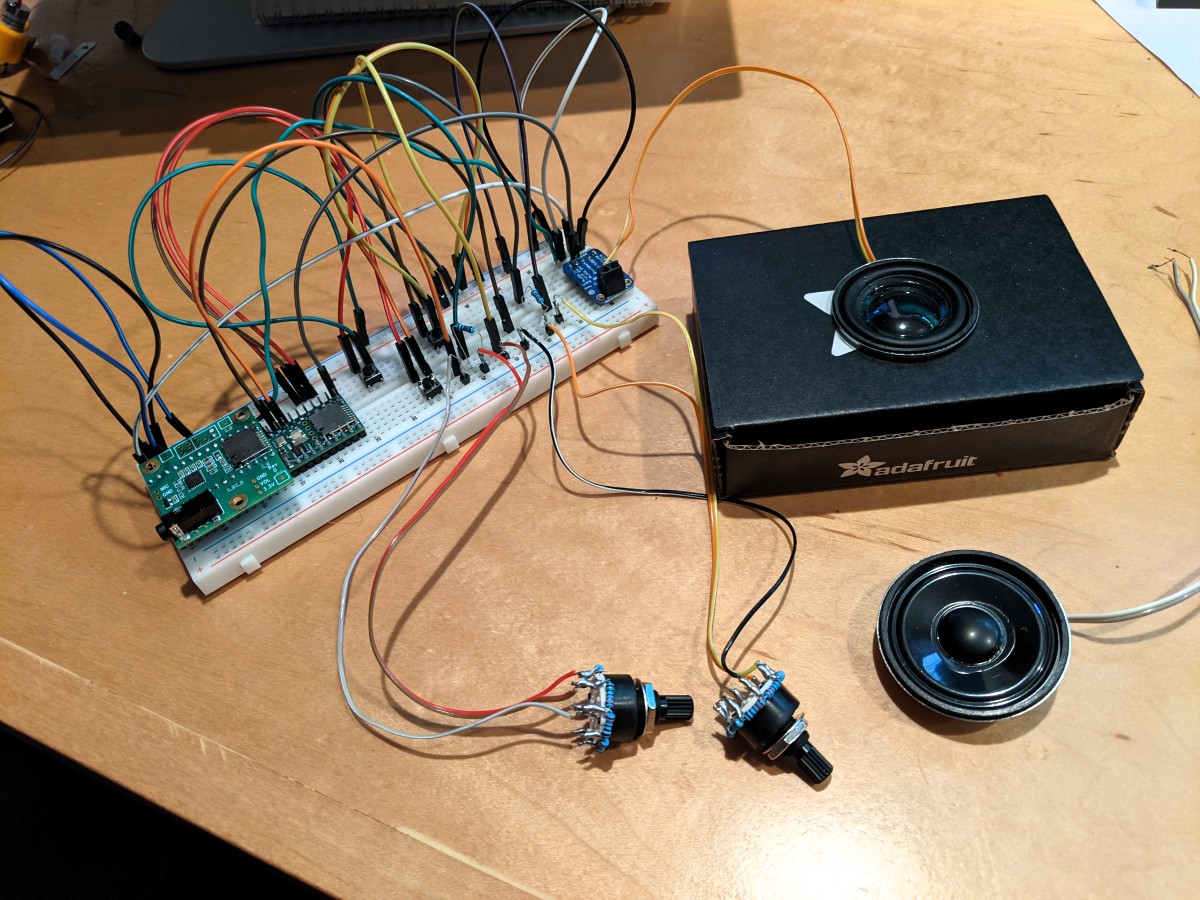
For the controller, I settled on the Teensy 4.1, a high powered ARM development board, and their audio adapter board.

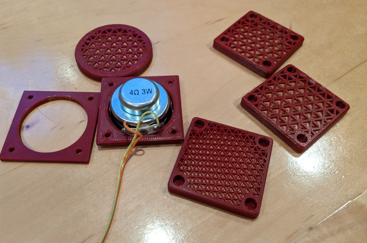
I chose a 2.5w class D amplifier and a 4ohm 3w speaker from Adafruit, as well as some 8 way rotary selector switches, and a potentiometer.

I purchased the PCBs for the keyboard itself from the designer. While it acts as a resistor ladder by default, I had enough open pins on the Teensy to allow one input per key, so I didn’t bother to wire up a matrix.

Keyboard PCB from Oskitone

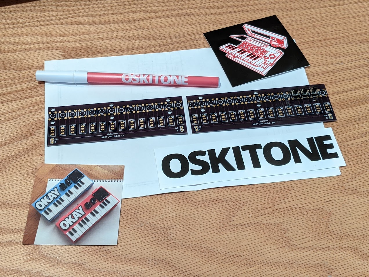
Ideally, I’d have had a couple of custom PCBs made that would have simplified the wiring and build a lot, but at the time I had not done so before.

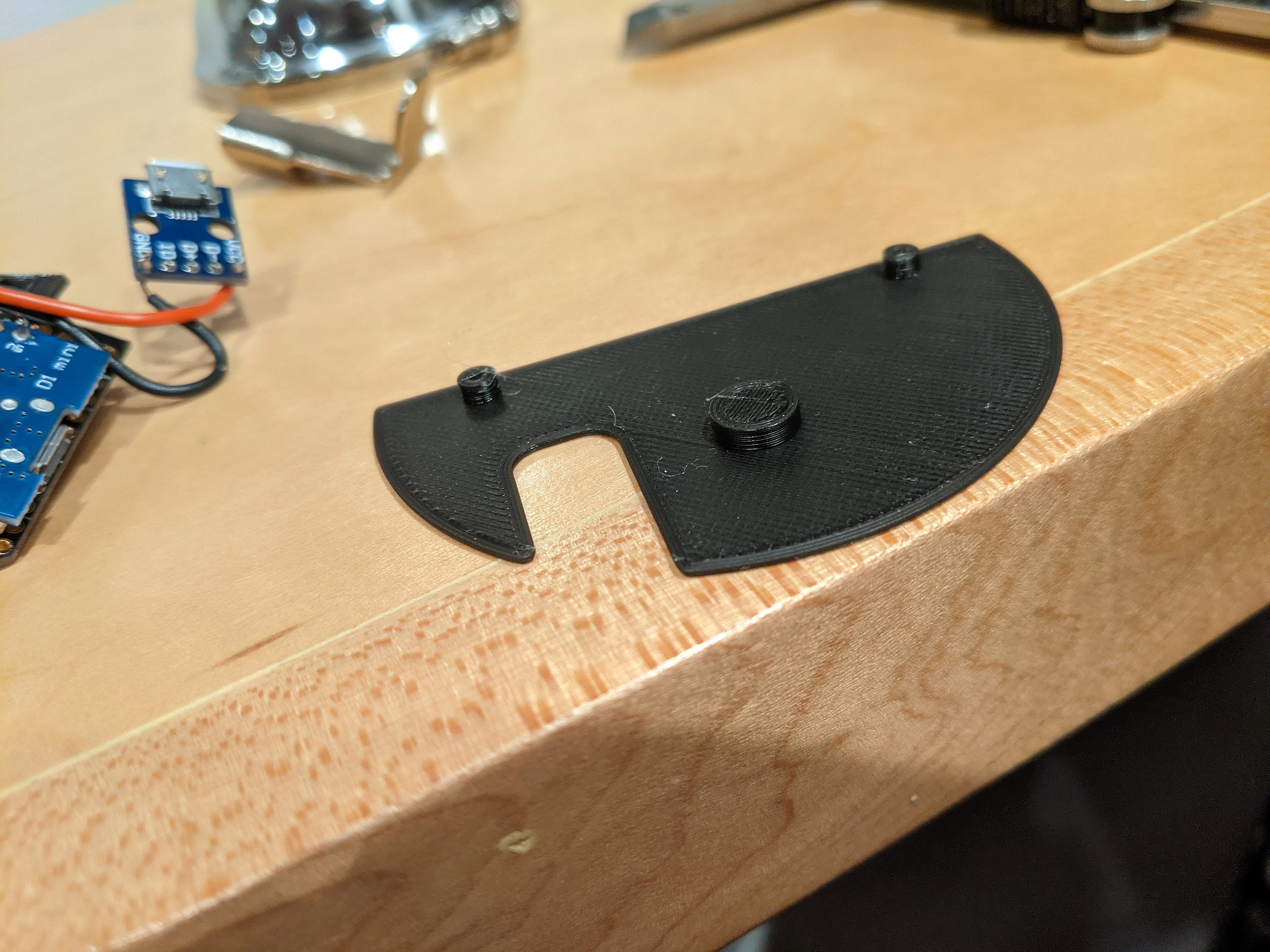
I made a handful of tiny changes to the case to accommodate my parts, mostly adding board standoffs in the right location, moving and adding potentiometer/switch holes in the lid, and resizing the hole for the speaker to match the one I used.

Testing speaker grills

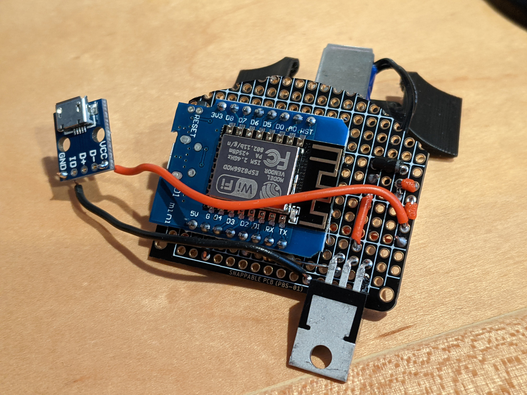
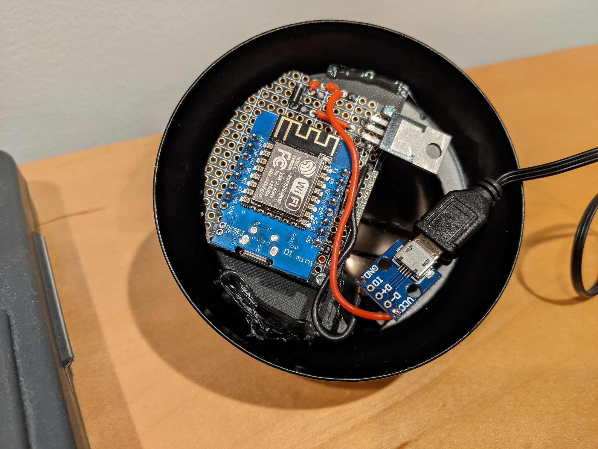
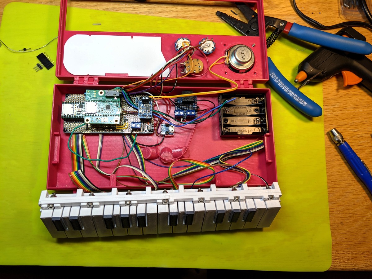
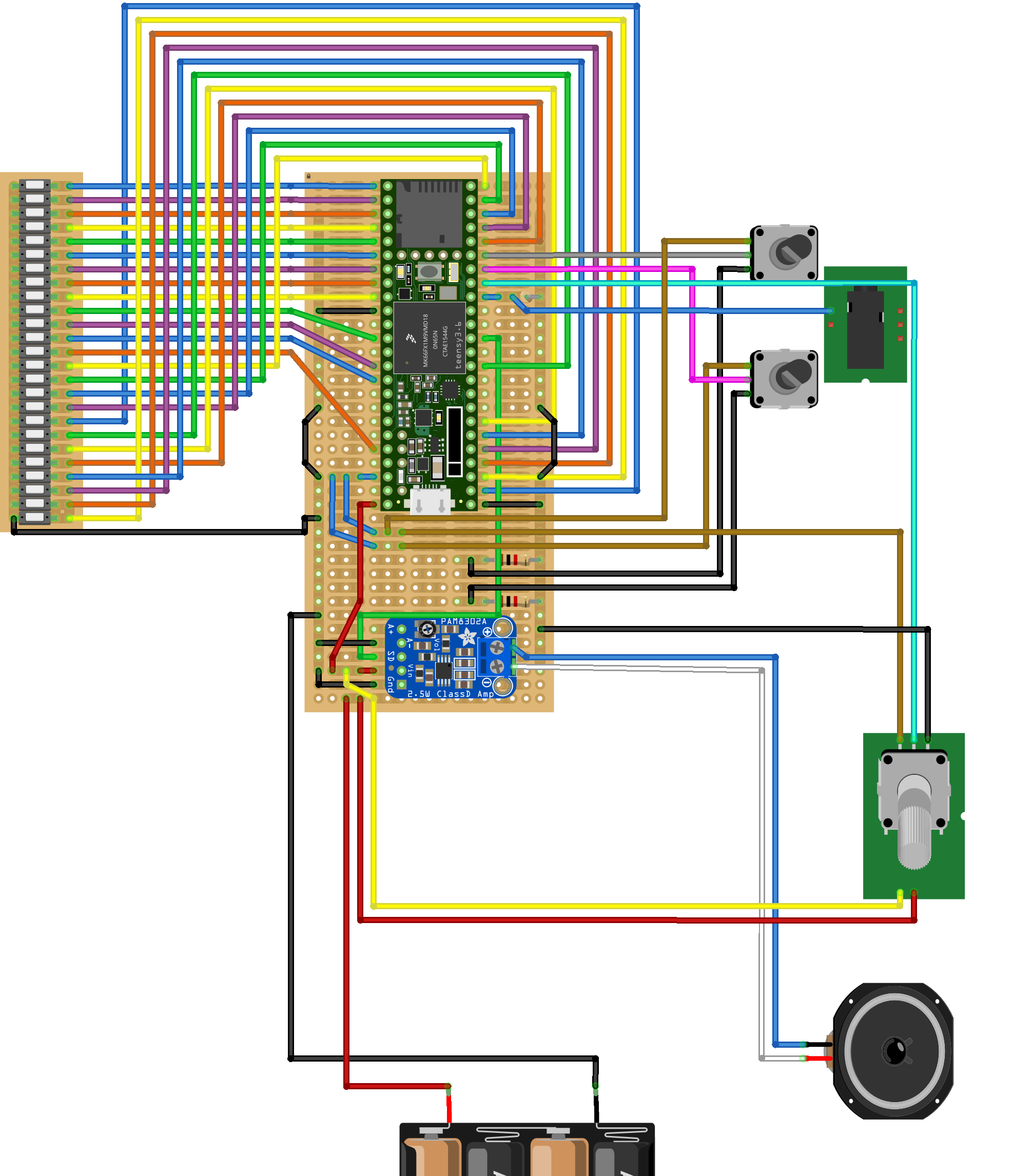
I soldered everything together on a protoboard.

For power, I’m using 4 rechargeable AAA batteries.

Software

The project code is available here: https://github.com/Billiam/okay-teensy

All together now

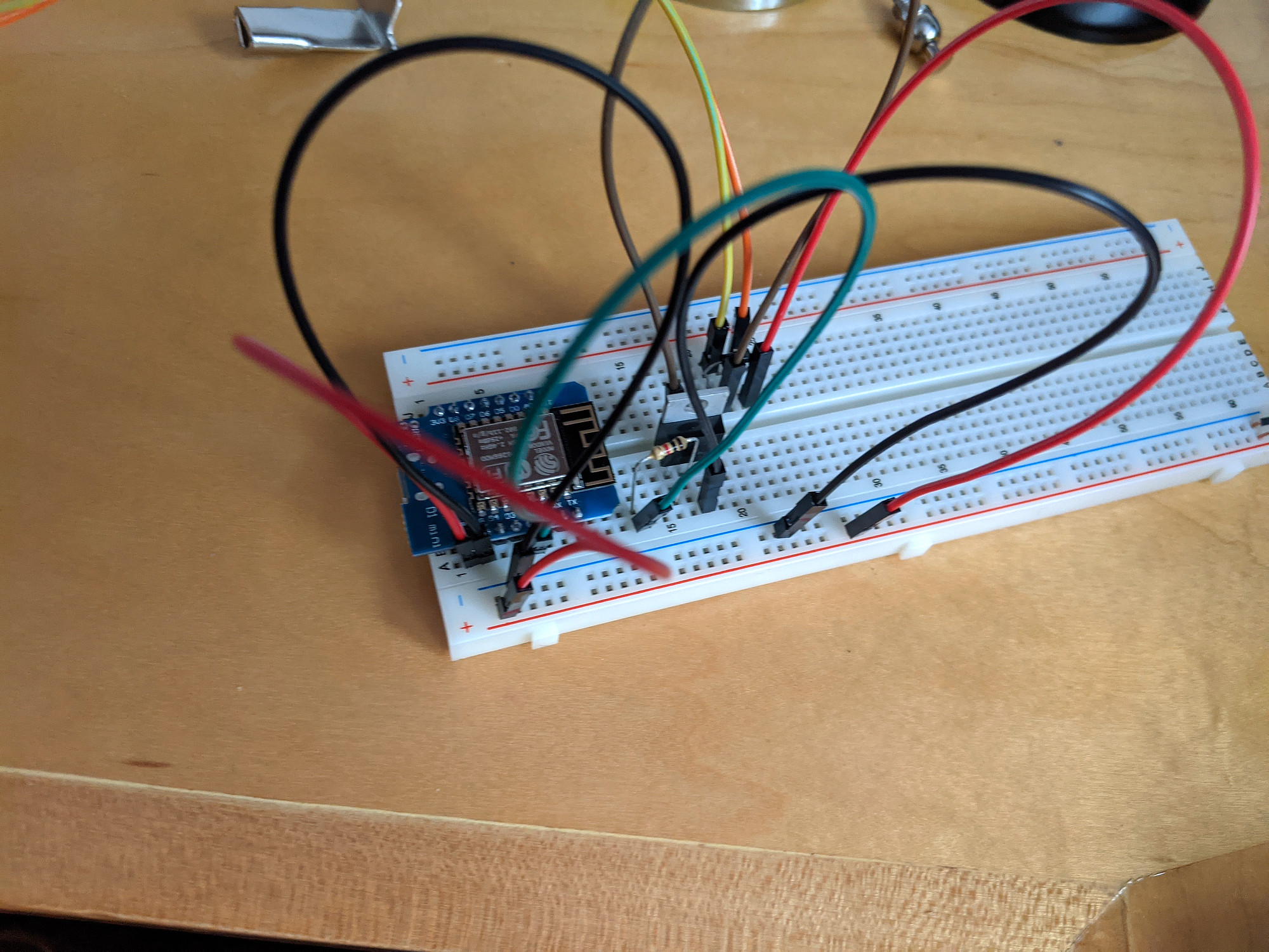
Initial breadboard testing

Breadboard, now with volume and selector switches
Breadboard diagram
Breadboard diagram

Done!


Grbl smooth jogging

I’m working on a pendant for my CNC, running Grbl 1.1f, and wanted to add smooth multiaxis jogging. I’ve already done a single axis implementation for this project: https://github.com/Billiam/cncjs-pendant-keyboardreader

This took me a little bit to find my way through, so I’m documenting it here.

Here’s a good introduction to the feature: https://github.com/gnea/grbl/wiki/Grbl-v1.1-Jogging

Smooth jogging implementation

This implementation uses the GRBL 1.1 modal jogging functionality, but not the \x85 jog cancel feature, which has not yet been added in CNCjs at the time of this writing. cncjs#512

note: Decimal places below are rounded for simplicity

For a single axis

The goal here is to send frequent, small jog commands at the frequency that we expect grbl to execute them. Without jog cancel, there will be some amount of overtravel equal to 0.5 - 1.5x the update frequency (not counting network latency).

My setup includes some wifi usage, so my update frequency is relatively high at 150ms. For direct-only connections (like a touchscreen connected directly to the cncjs server), this could and should be much lower and will feel more responsive to both starting and stopping.

To move one axis at 500 mm/min, divide the total distance to travel in a minute by the update interval to get the total distance to travel for the interval `(500_("mm")) * (150 // 60*1000) = 1.25_("mm")// 150_("ms")`

And then issue the jog command: $J=G91 X1.25 F500, and then continue issuing the same jog command every 150ms until you want motion to stop.

I issue the first delayed jog command with a reduced delay, about 100ms instead of 150ms. This helps to keep grbl’s buffer full, so that it doesn’t try to decelerate each jog step to a stop, which results in jerky movement. This reduced delay should ideally be based on axis acceleration settings and variation in latency.

When (and if) jog cancelling is added in cncjs, the cancel command could also be added at the end of movement. Ideally, this would also allow you to exceed the requested travel distance for smoother jogging, since a jog stop could be issued when needed.

I haven’t come up with a way to do this safely that wouldn’t result in dangerous overshooting if the jog cancel command failed, or when using multi-axis jogging (below) though.

For multiple axes

Multiple axis smooth jogging is a little more complicated. I also want the Z axis to move about 4 times slower than the much larger X and Y axes, meaning I’ll have a ratio of axis speeds like x:y:z -> 1 : 1 : 0.25.

This is also important if using a multi-axis analog controller like a joystick/gamepad, or some wild 3+axis one: Each direction component will have its own speed relative to the others.

When you give grbl a jog command: $J=G91 X5 Y5 Z5 F500, the total distance traveled will be `D^2=x^2+y^2+z^2`, or about 8.66mm, since it moves in a beeline from the starting position to this offset.

To get the desired jog distance for each axis (with different travel speeds), we have to do some math.

First, we can get the diagonal of a rectangular prism with side lengths of of x1, y1, and z1 from our speed ratios, `D = sqrt(x1^2 + y1^2 + z1^2 + "…")`. This represents the relationship of 1 unit of axis speed to the diagonal travel.

For my speeds, that’s `D = sqrt(1^2 + 1^2 + 0.25^2)`, about 1.436.

To get the actual X travel distance, it’s the X speed ratio (1), the X direction(-1 or 1), and the desired travel speed, and the diagonal component: `X_("axis travel") = (500 * -1 * 1)//D` for a total of ~348mm/min, or -0.87mm/150ms.

The slower Z axis can be calculated the same way: `(500 * 1_("direction") * 0.25_("speed"))//1.436`, or 87 mm/min, but we also know its speed is 0.25 × the X axis speed, so 0.25 × 348: 87 mm/min (0.2175/150ms).

This gives us the jog command: $J=G91 X-0.87 Y0.87 Z.218 F500.

Grbl will plan this move so that all axes arrive at the same time, and everything works great.

However, note that $J=G91 Z.218 F500 would not be correct for this feed rate, and will complete much more quickly than our 150ms interval, causing stuttering motion.

Instead, the feed rate needs to be reduced to the maximum speed of all the axes being moved (in this case, just 0.25 × 500): $J=G91 Z.218 F125.

This applies to multi-axis moves as well. If the speeds being used were y:0.6, z:0.25 (with no X component)

`D_("distance")^2 = 0.6^2 + 0.25^2 = 0.65`
`Y_("axis") = (500 * 1 * 0.6)//D = 461.55_("mm/min") (1.15//150_("ms"))`
`Z_("axis") = (500 * 1 * 0.25)//0.65 = 192_("mm/min") (0.48//150_("ms"))`
`F_("feedrate") = max(0.6, 0.25) * 500 = 300`

Result: $J=G91 Y1.15 Z0.48 F300


CNC tramming plate

Note: This is an older (2+ years old) project, and there are now better third party options available (check Millright groups on facebook), even completely replacing both the Z plate and router mount with significantly beefier aluminum parts free of these issues.

There are a couple of problems with the default router mount on this CNC.

The first is that none of its sides are parallel. When mounted to the Z-axis plate, it visibly dives downward in the front toward the spoilboard.

The surfaces that contact the router are also tapered inward, so any adjustment to the router clamping has a tendency to shift the router in one direction or another.

Both of these issues can be shimmed (somewhat), but since the router mount bolts through the Z plate from behind, it takes a lot of work to disassemble the Z axis, loosen the router mount, shim behind it, tighten back up, and reassemble before checking tram again.

The first pass I made at fixing this used a 3d-printed collar, positioned above the router mount with a few adjustable screws to adjust the offset. The idea was that the collar could be tightly fastened to the router, adjusted, and held down firmly while tightening the router mount’s clamp to make fine adjustment more reliable. This helped, but ultimately not enough. I think this could have worked with an aluminum collar, and with holes threaded from the top into the router mount so that manual downward pressure wasn’t required.

3d-printed adjustment collar on top of stock router mount

In the end, I replaced the stock router mount with this (well machined) OpenBuilds router mount instead. The diameter is slightly oversized for the DWP611 router I’m using, so I 3d-printed a thin (~1-2 mm) straight shim for it.

To mount this to the router, and allow easier tramming in both the X and Y axes, I’ve designed this plate that will bolt to the Z-plate through the front. This allows shimming in the Y axis by just loosening the plate from the front, adding shims, and tightening back down.

Replacement plate and router mount attached to stock Z plate

For the X axis, I’ve added overside holes to allow the use of eccentric nuts for adjustment.

This did require drilling and tapping 4 new holes in the stock steel Z-plate, but that went fine going slow and careful (and using a drill press to keep the tap straight).

Here’s the first side cut from 3/8” aluminum. As this is a (not yet installed) tramming plate, please excuse the surface finish.

Back side of tramming plate with bored holes for mounting and clearance

To cut the opposite side to size, and chamfer the edges, I cut a pocket in scrap MDF both for workholding and to position the part. This mostly worked but I did end with a small gouge on one side, when (I think) the part shifted a little bit.

Chamfered edge of visible side of plate

I also cut these two tiny wrenches to help adjust the eccentric nuts.

Small wrenches for eccentric nut adjustment
Adjustment wrench in use

Overall, this has made a huge improvement in the time required for tramming/squaring and I’d highly recommend it (or replacing the stock Z plate entirely) if you’re having similar issues.


I’ve released a few projects I’m using for managing projects and games on itch.io.

itchpack

The first is itchpack, commandline, preconfigured wrapper around webpack with some extra utilities.

Itchpack provides a local development environment for game, gamejam, and profile pages on itch.io.

It downloads your current page markup and styles, can render templated data from a data file, prefixes custom- in front of your HTML classes, handles sass/scss compilation, and provides live reloading when working locally.

I used it extensively while working on the game page for Deepdwn.

itch_client

itch_client is a ruby library for interacting with itch.io. There are some functions I needed for the next project which are unavailable in the itch API.

itch_client is a screenscraping client and provides authentication, updating and fetching reward information, as well as purchase and reward redemption logs.

itch-rewards

itch-rewards is a commandline application based on itch_client, meant for automating available game page rewards, especially for community copies.

itch-rewards allows a game developer to set a minimum number of copies that are always available, or to have the number update based on sales (for instance: “Every copy of my game sold makes a community copy available!”), or based on tips above the game price (configurable).

itch-rewards can also update the reward content itself, to show the number of copies that have been made available, or progress to the next copy.

I’m using this in concert with the script used for my desk bell notifications to update available rewards after purchases.


An itch.io project of mine has been getting a little attention recently, and I wanted to get alerts for new purchases, instead of obsessively checking the website. I saw this kickstarter alert desk bell project a few years ago, and thought it would work great.

Here’s my finished project:

It runs a web server waiting for a JSON payload, and then rings the bell the appropriate number of times.

Build

Parts list:

  • $3 Wemos D1 clone arduino board
  • $5 5v mini solenoid. This is perfect for this use case
  • 1k resistor
  • TIP120 transistor
  • 1n4004 diode
  • Electrocookie solderable perfboard (really nice)
  • USB breakout board from another project.

To mount the solenoid to the bell frame I 3D printed a small mount. The solenoid frame had two M2 threaded hole that made mounting easier. The mount clips onto the frame, but ought to sit a few mm lower. The nice thing about this design is that the bell can still be used normally if needed… Not sure when I’d need that.

3D printed mount attached to desk bell

I did a bunch of tests on a breadboard since I’m still new to electronics projects, first with just the solenoid to make sure it would ring clearly and later with the arduino. I did most of the design with a NodeMCU but switched to the smaller Wemos D1 when I ran out of space.

Testing the circuit on a breadboard

One thing I didn’t anticipate when I started is that the clapper (the part of the bell that swings) sits low into the the bottom base in its resting position. This reduced the available space underneath by about half, so I made a paper template and then cut an arc into one side of the (previously square) perfboard with a jewelers saw.

I also 3D printed this simple mount, mostly to keep any of the circuit from contacting the metal frame. The board holds to it nicely, but I haven’t designed a good mount for it, so I just hotglued it in place for now.

Small mounting plate for the board
Board done soldering
Mounted inside bell
Mounted inside bell

There’s more stuff I’d like to do:

  • 3D print the whole base for better mounting points and more space
  • LEDs (I have an LED ring that fits really nicely in the diameter of the bell, but there isn’t really enough room for it right now)
  • Proper outlet mounting instead of just sneaking a thin cable underneath the base

Software

For the firmware, I’m using arduino fsm to handle state changes and delays, since I want the solenoid to activate for about 150ms and then wait a couple of seconds before it can activate again. I need this to be non-blocking, so that I can also respond to web requests and later do some LED animation. The webserver and wifi code is mostly taken from the default ESP8266 examples.

For some reason, the D1 etc. pin constants did not work for me when using the Wemos D1 board profiles, using the correct GPIO pin instead did, so I didn’t investigate further.

It waits for a request with valid basic auth credentials, and a JSON body with a count value, ex:

curl -s -i -u username:password \
  --header "Content-Type: application/json" \
  --request POST \
  --data '{"count": 2}'